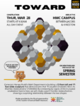

Announcing the Prisms of Eight Free Build
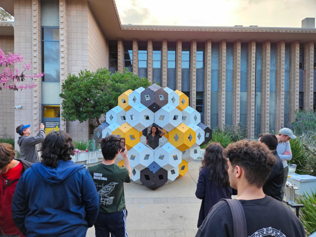
If you’re in the Seattle area, Studio Infinity and the Seattle Universal Math Museum will be hosting a freestyle build on Saturday, January 11th. We have absolutely no clue what this structure will look like when complete and would love for you to be part of the team that plans and executes its construction!
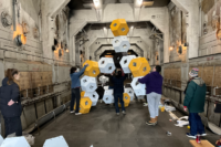
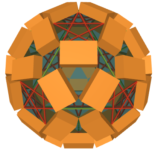
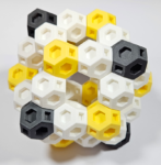
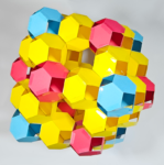
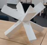
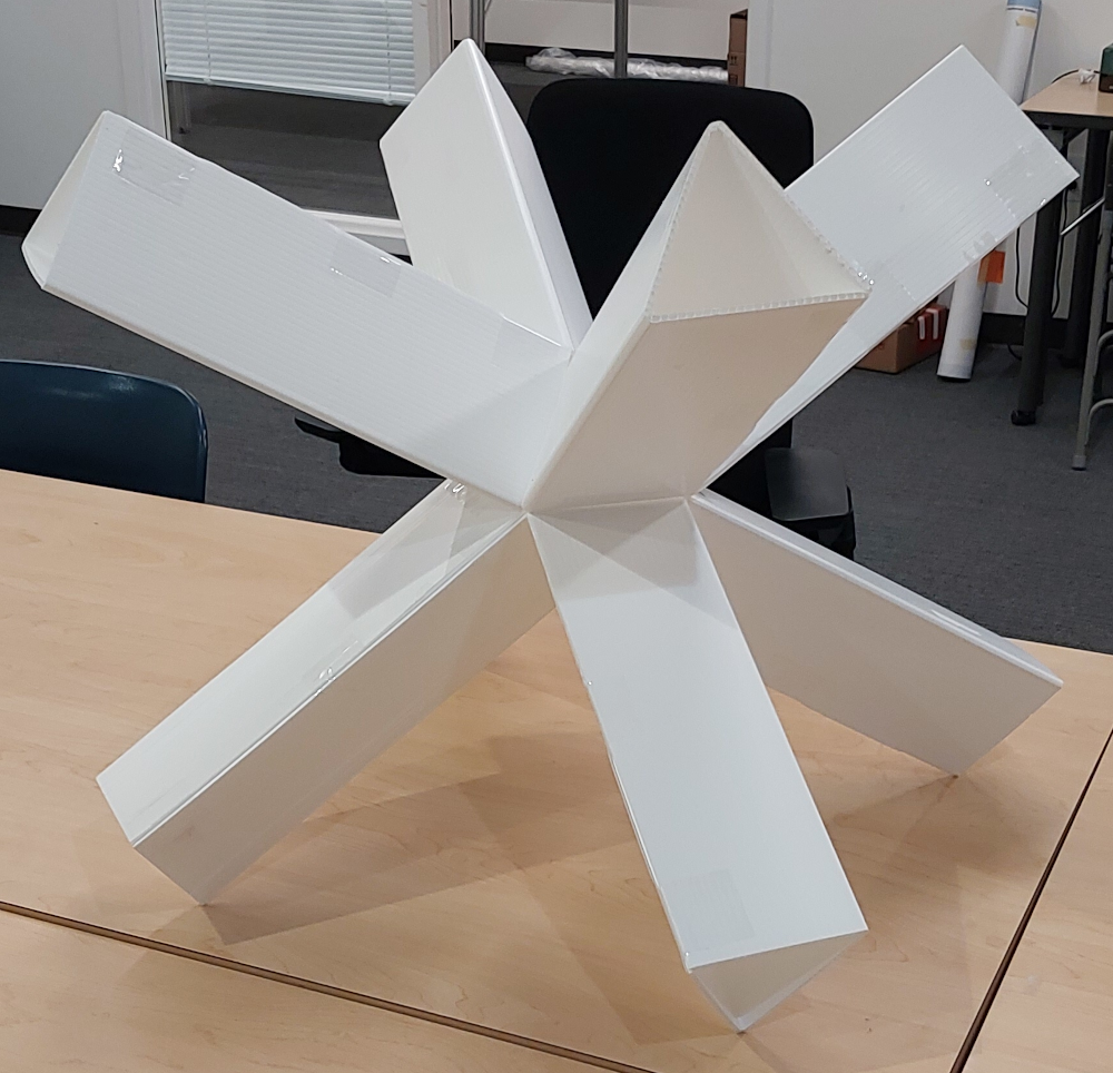
The unit we will be building with is a regular octahedral junction with eight triangular prismatic “arms” protruding from its faces:
We have a few ideas for what this building unit might be good for, but we are far more excited to see what a group of creative math enthusiasts can dream up.
The build will take place on Saturday, January 11th from 9:00am to 12:00pm in the 4th floor exhibit hall of the Seattle Convention Center. While the Joint Math Meetings have a registration fee the rest of the week, entry to the exhibit hall is completely free this Saturday. There will be many cool mathy things in the exhibit hall for both children and adults to enjoy, so bring friends and family of all ages!