Fort Sierpinski
I’ve used a lot of different materials to build Sierpiński Tetrahedra over the years, including mailing tubes and hula hoops, among other possibilities.
Read More

I’ve used a lot of different materials to build Sierpiński Tetrahedra over the years, including mailing tubes and hula hoops, among other possibilities.
Read More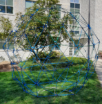
For this installation commissioned by the Dickinson College mathematics department, we chose a construction technique that goes all the way back to a construction from 2016, but this time with a twist. All previous installations done with this technique used only one length of rod, producing rigid equilateral polyhedra. But I had long wanted to construct a rhombic enneacontahedron, a shape that George Hart introduced me to with one of his artworks.
Read More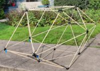
I will be leading a group construction of a 3.4m diameter rhombic enneacontahedron next Tuesday, 2022 Oct 11, on the campus of Dickinson College. This is the first time that I will be leading a construction using this system — dubbed ZipStix at the NYC math museum — with rhombic faces rather than regular polygons.
Read More