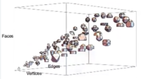
Studio Infinity is pleased to announce the preparation of a new traveling art/science exhibit, Polyplane. The producers, Alex Kontorovich and Glen Whitney, are seeking submissions of physical polyhedra to become part of the exhibit. A broad variety of media and styles are welcomed, in support of the central aims of Polyplane: to celebrate the beauty of geometric forms while allowing visitors to directly perceive a fundamental law that governs them, Euler’s Polyhedron Formula. For more information and to reserve space for the polyhedron of your choice, visit polyplane.org.
Hey, I have recently become the Problem Warden for the Prison Math Project (PMP). That means I’m the editor of The Prisoner’s Dilemma, the quarterly problem section of the PMP newsletter. So I’d love it if you have intersting problems or mathematical puzzles to submit to the column. Of course, you will be credited online and in the newsletter for any problems you submit.
I also welcome solutions to the existing problems from anyone. Problems range in difficulty from high-school contest level up to roughly the easiest end of Putnam competition problems. So to submit problems or solutions, please email me at dilemma “at” pmathp “dot” org. Looking forward to your ideas!
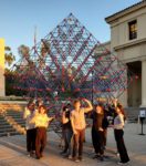
Over fifty members of the Occidental College community, organized by Prof. Jim Brown of the Math Dept., came together (Friday, 2023 Nov 10) to construct a Sierpinski-style fractal based on the regular octahedron. You can read more about it in the The Occidental weekly newspaper; more details will be posted here as time permits. But here’s the completed structure:
This construction event closed with a dramatic denouement. Studio Infinity had recommended an ambitious plan to support the resulting 17-foot-tall structure on a single vertex of the outermost octahedron, facilitated by the custom wooden cradle (fabricated by Pablo and Ricardo Lopez) that you can make out at the bottom center of the photo. This scheme worked perfectly through the third iteration of construction (out of four doublings of the size of the structure). But then:
This sculpture was just on the edge of stability — the structure was self-supporting up until the very final module, and the team was able to lift and carry it to place it atop that final module. However, once those lowest connections were made, the torque on them proved too great for the tolerances of the system being used.
The upshot is that if Studio Infinity leads another build of this intriguing fractal, it can be placed on one of its faces, rather than on a vertex, and it will remain stable. That feeling of real-time experimentation is one of the things that makes public sculpture-raising like this so exciting!
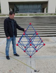
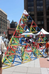
Studio Infinity has teamed up with Prof. Jim Brown and the Occidental Math Dept. to create the Oxyhedron on Friday, 2023 Nov 10, starting at 10 AM. The installation will take place just outside Fowler Hall, which houses the Math Dept. I did a site visit today; on the right you can see the quarter-scale mockup being used as a stand-in to plan the event, held in place by Jim.
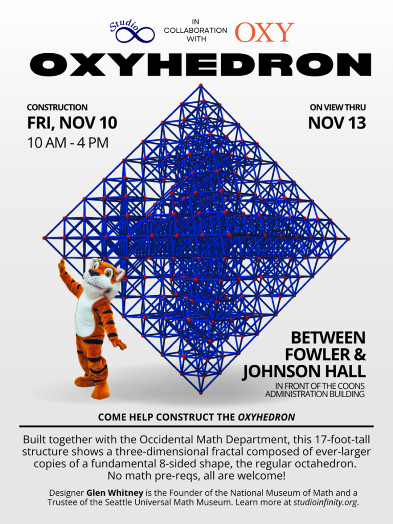
The structure we’ll be building is the octahedron analogue of the Sierpinski tetrahedron that formed the basis of Fort Sierpinski on the campus of Lafayette College last fall. It will consist of 1,968 rods and 457 hubs from The Ultimate Fort Builder construction set distributed by Lakeshore Learning.
Below is the poster announcing the build (note the image is to scale). Anyone reading this who will be in the area on Nov 10 is welcome to attend. More details and pictures will be posted as the event unfolds.
I’ve been the primary architect of a number of constructions of
So when I discovered that the Lakeshore Learning Ultimate Fort Builder construction toy allowed rods to be connected at all of the angles necessary to construct arbitrary portions of an octahedral-tetrahedral lattice, I knew that I had no choice but to eventually seek yet again to scale this tower of three-dimensional fractality.
The opportunity came in the fall of 2022, when my colleague Prof. Alissa Crans put me in touch with Profs. Derek Smith and Ethan Berkove, who were interested in holding a collaborative mathematical construction outside the math department’s building on the Lafayette College campus. After reviewing a number of proposals, they (to my delight) selected a Sierpinski tetrahedron constructed from the Fort Builder toy. They felt this structure would tie in to a number of classes being held that semester, including one on combinatorics — just how many rods and joints are there in that pyramid, anyway?
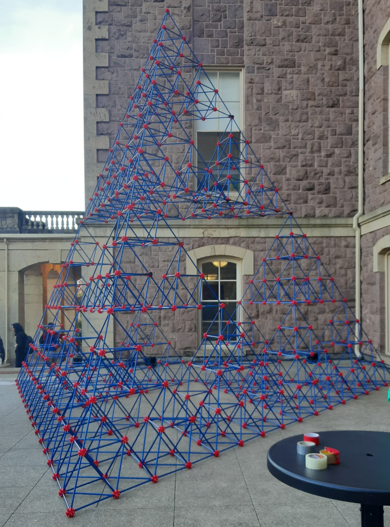
This post will be fleshed out as time permits, but for now suffice it to say that the construction — quickly dubbed Fort Sierpinski — came together very satisfyingly (more below).
The final structure came in at just a few inches shy of twenty feet tall, making it the largest Sierpinski tetrahedron I’ve been involved in yet, as well as the highest-order approximation: there are five generations of tetrahedra, from the smallest unit tetrahedra to the construction as a whole.
If you look closely, you will find just a few connections where the ability of the hub-rod sockets to take tension trying to pull them apart had to be augmented with a little strategically-placed tape (as hinted by the items on the table in the foreground). Other than this kind of patching (after all, kids do have to be able to take their creations apart by pulling out the rods, and this giant building is putting a lot of tension on certain junctions), the Fort Builder toy turned out to be quite up to this gargantuan task.
For this construction commissioned by the Dickinson College mathematics department, we chose a construction technique that goes all the way back to a construction from 2016, but this time with a twist. All previous installations done with this technique used only one length of rod, producing rigid equilateral polyhedra. But I had long wanted to construct a rhombic enneacontahedron, a shape that George Hart introduced me to with one of his artworks. Although that polyhedron is equilateral, consisting of 90 rhombi of two types, it is not rigid by Cauchy’s Theorem on polyhedra: each face is a quadrilateral, and so no face is by itself rigid. Hence, it’s necessary to brace the rhombic faces. Since there are two different face shapes, that means there are two additional rod lengths for the lengths of diagonals of those two different rhombi.
Further, the sponsors decided to proceed with a design in which the rods were colored to correspond to the ice caps, land masses, and oceans of our planet Earth, in honor of the world in which we live and a contemporaneous conference on climate change and other ecological issues.
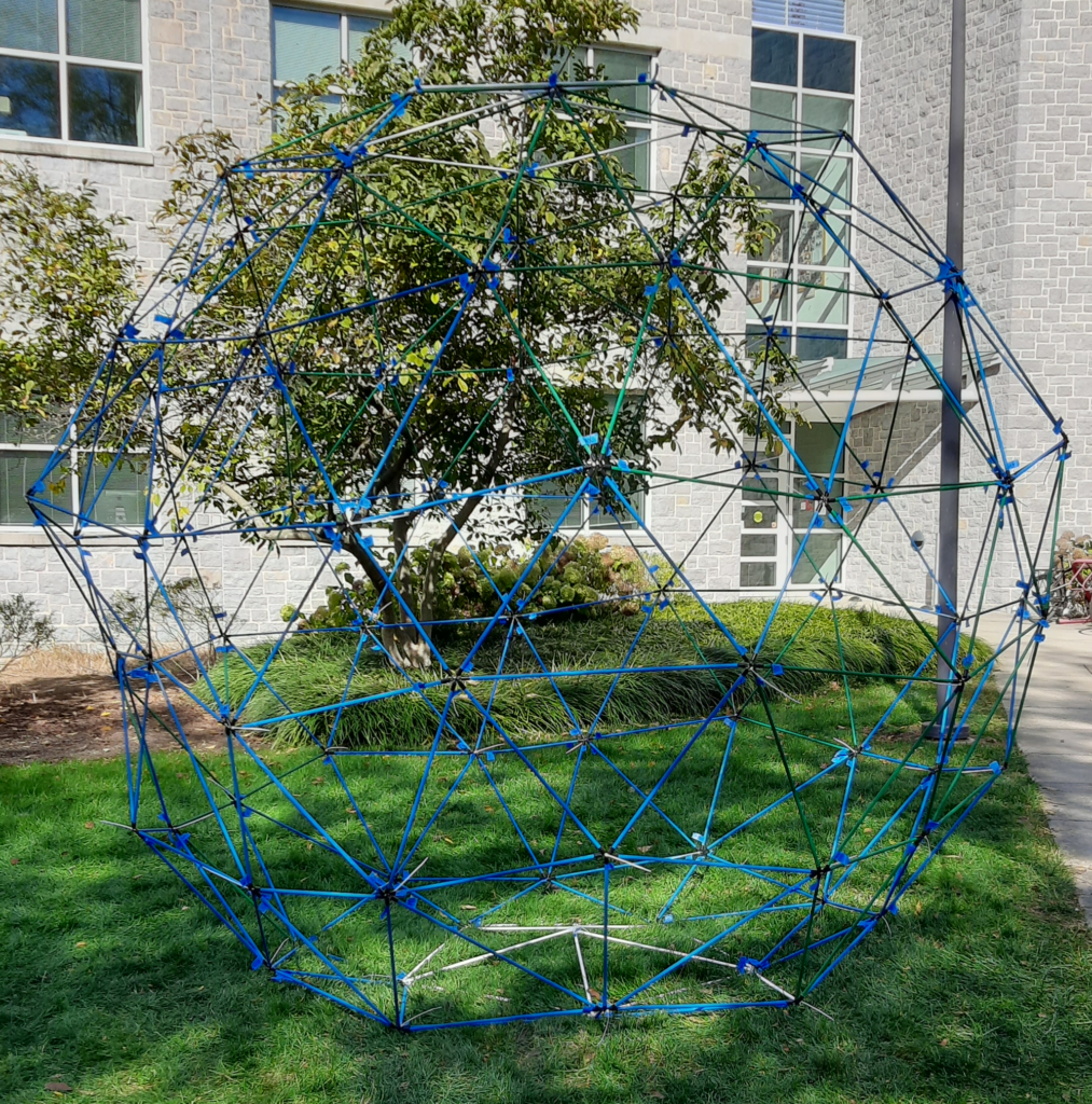
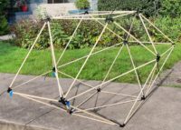
This post will be fleshed out as time permits, but here’s a picture of the completed construction on site at Dickinson college (more below):
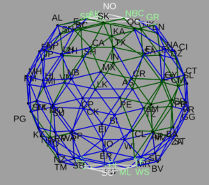
This photo is taken from a viewpoint over the southern tip of Mexico and the Central American land bridge to South America (since there are “only” 180 edges to this polyhedron, the representation of land masses is by necessity quite approximate). For comparison, here’s an image of the pre-build rendering of the Rhombiglobe from essentially the same viewpoint:
You may notice the actual construction has a decidedly “non-spherical” aspect on its left, in the midst of the Pacific Ocean. That phenomenon was perplexing in the midst of the build, but later analysis revealed that it was a direct side effect of there being nine different types of pieces: three colors of rod in three lengths each. One of the participants in the group construction inadvertently swapped one of the longer and one of the middle-sized blue rods in the neighborhood of the bulge. The result was that by dint of perseverance, we managed to construct a geometrically “impossible” polyhedron, which naturally adopted a non-spherical shape as it attempted to resolve all the extra stress that the incompatible edge lengths created.
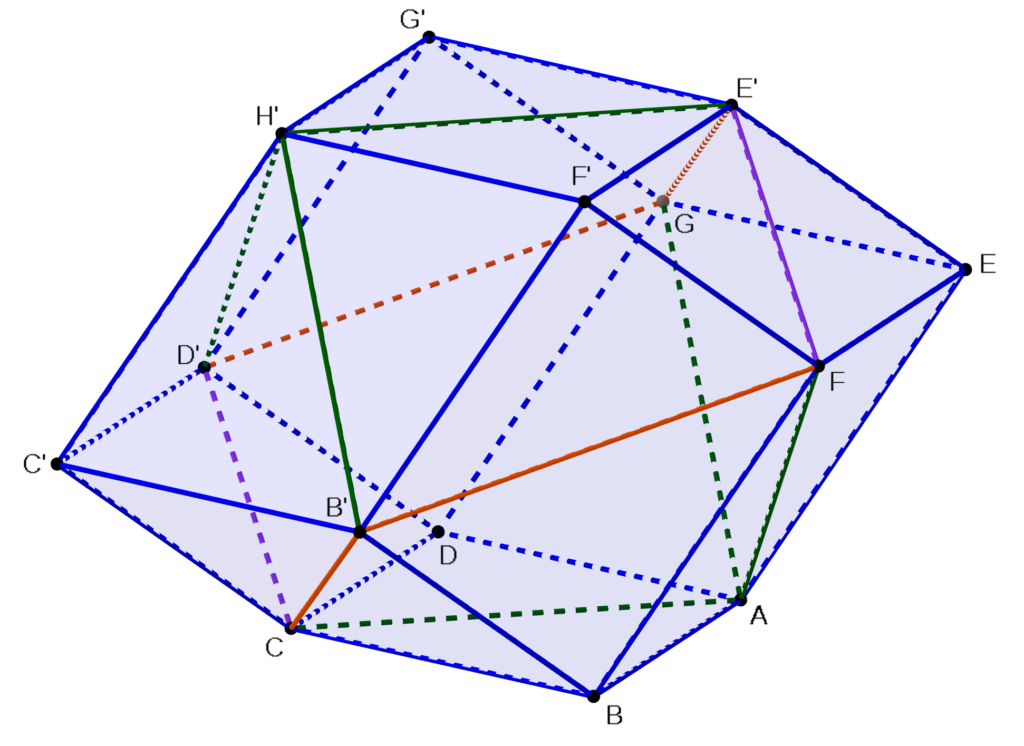
I will be leading a group construction of a 3.4m diameter rhombic enneacontahedron next Tuesday, 2022 Oct 11, on the campus of Dickinson College. This is the first time that I will be leading a construction using this system — dubbed ZipStix at the NYC math museum — with rhombic faces rather than regular polygons. So to prepare, last weekend I built the prototype you see in the diagram at right. It has twelve faces (hence the post title) and uses both of the rhombus shapes that appear in the enneacontahedron, as well as a third rhombus that is almost, but not quite, a square. Here are the complete build instructions.
Materials
Tools
24 wood dowels, 2′ long by 3/8″ diameter
small handsaw for cutting dowels
Enough additional dowels (e.g., 11 dowels 3′ by 3/8″) to cut the following lengths:
light hammer for tapping caps onto dowels
4 dowels 32 3/4″ long, 6 dowels 27 3/4″ long, and 2 dowels 17 1/8″ long
(optionally) angle brackets for backing up caps when tapping
72 plastic end caps for 3/8″ diameter dowels, similar to these
(optionally) instant-setting glue for caps that slide off during construction
14 “zip-style” cable ties
easily-removable tape (like painter’s tape) and markers for labeling parts during construction
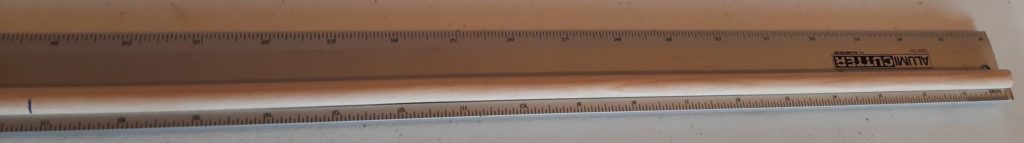
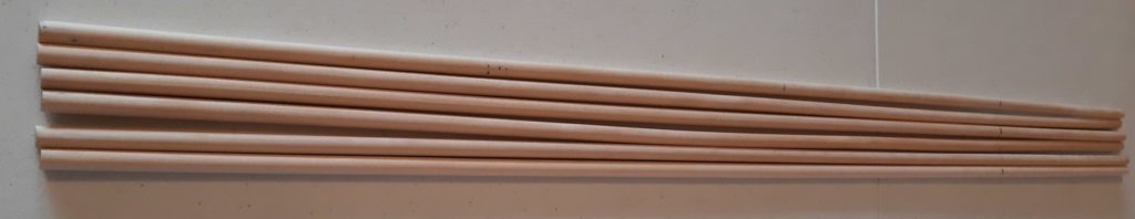
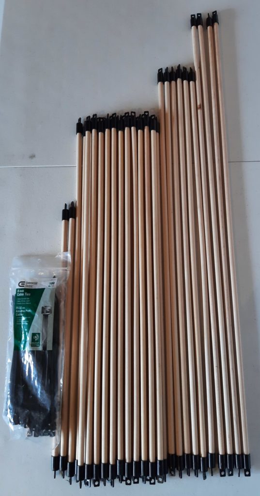
First, measure the lengths of all the dowels you need to cut. Here’s one of the 17 1/8″ dowels being measured (you can get two of these from opposite ends of one 3′ stock dowel), and below that, all of the 27 3/4″ dowels ready for cutting.
Next, cut the dowels to the marked lengths, and insert each end of each dowel into an end cap. Depending on the tolerances of the end caps and the dowels, you may be able to do this by pushing the caps on firmly by hand, or you may need to tap them on with a light hammer. In the latter case, you probably need to brace the caps against something to avoid breaking the tabs on the plastic caps. So place a right-angle bracket that is at least as wide as the tab is long on a flat work surface (so that the right angle is against the table), place a cap with a partially-inserted dowel so that the flat part of the cap at the end of the tab is against one arm of the bracket, and tap the other end of the dowel. To get the second cap on, first make sure that the two caps are roughly “lined up” so that their tabs are more or less in the same plane. Then, you will likely need to hold another bracket against the end cap at the other end of the dowel to have a surface you can tap on (watch your fingers!).
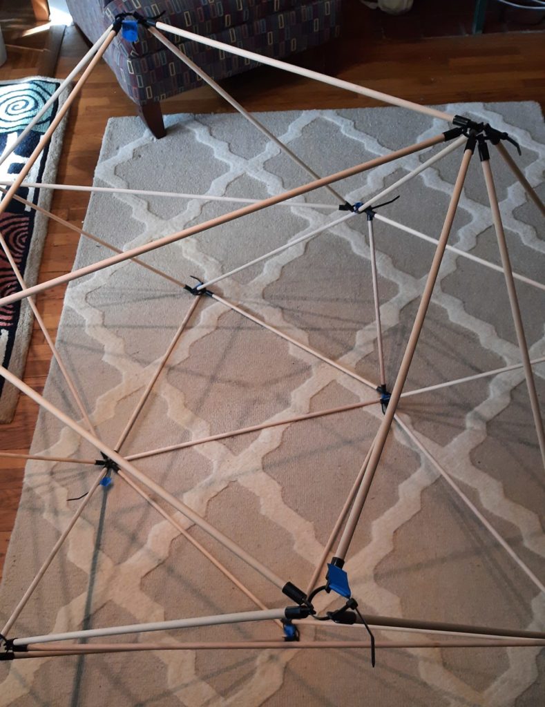
At left you can see all of the dowels cut, capped, and ready to go, together with the bag of cable ties we’re going to use. The assembly will proceed from vertex to vertex in the diagram above — you probably want to print out a copy to be able to refer back to it as you go through the construction process. The edges (dowels) in the diagram are color coded by length: The longest edges are orange, the six slightly-long ones are green, the 24 two-foot edges are blue, and the short edges are purple. So in the directions below, we will refer to the dowel lengths by the colors in the diagram (even though the dowels themselves are not colored). Also pay close attention to the letters labeling the vertices in the diagram. Note there are A through G and B’ through H’; the ones with “primes” on them are different from the ones without. During construction, the outside of the polyhedron will be lying on the floor as you build these vertices, so you’ll be standing and looking at them as if you were inside the polyhedron. Therefore the order that the edges are listed for a given vertex is the order that you would see them surrounding that vertex if you were standing inside the polyhedron looking outward at the vertex.
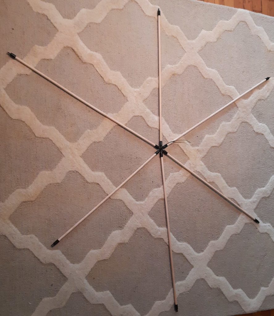
So start (step 1) by lacing a cable tie through the holes in the end caps at one end of dowels of the following lengths in order: green, blue, green, blue, green, blue. That creates vertex “A.” Feed the cable tie through its own end to secure it, and pull it some of the way through but do not pull it all the way tight yet — we will tighten up all of the vertices at the end of the construction. You should end up with something like the picture at the right. And now, it’s very important that you label the vertex you just made as vertex “A” (mark an “A” on a piece of tape and wrap it around one of the dowels at the vertex) because you will need to refer back to that vertex later in the construction.
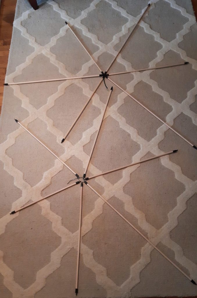
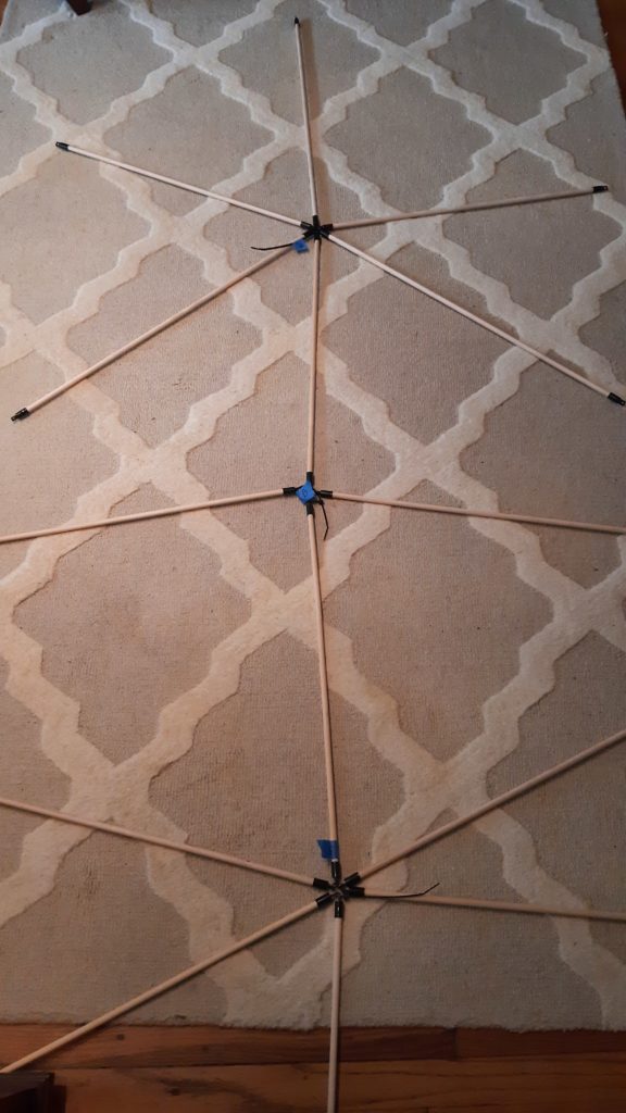
Put vertex A aside for now, and construct the following vertices (each one separately) in the same way. Remember to label each vertex as you make it! (Step 2) Vertex B’ with orange, blue, green, blue, orange, blue. (3) Vertex D’ with orange, blue, purple, blue, green, blue. And (4) vertex E’ with orange, blue, green, blue, purple, blue. At left are pictures of these three vertices (not labeled yet, so we had to go back and figure out which was which and label them after the fact — spare yourself that chore).
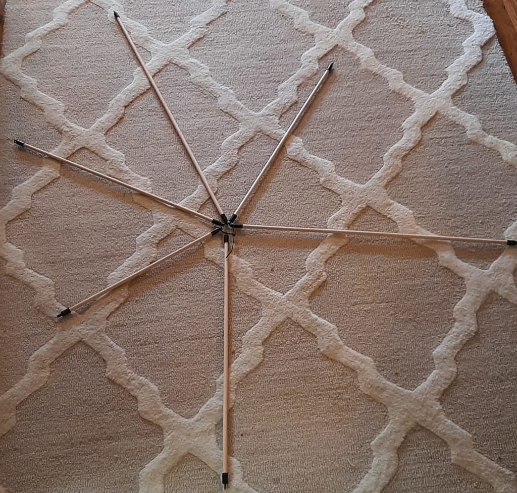
Now for (step 5) find vertex A and vertex B’ and arrange them so that the free ends of one of the blue-length dowels of A and the blue-length dowel of B’ that is between the two orange-length ones are near each other. Thread a cable tie through these free ends, including one fresh blue-length dowel between those two and one more fresh blue-length dowel after the second one. Close up the cable tie and pull it partway closed like you did with the first four vertices. Immediately label the new vertex you just created “B”. Your outcome should look similar to the picture at right (see, we finally got our labels straight!).
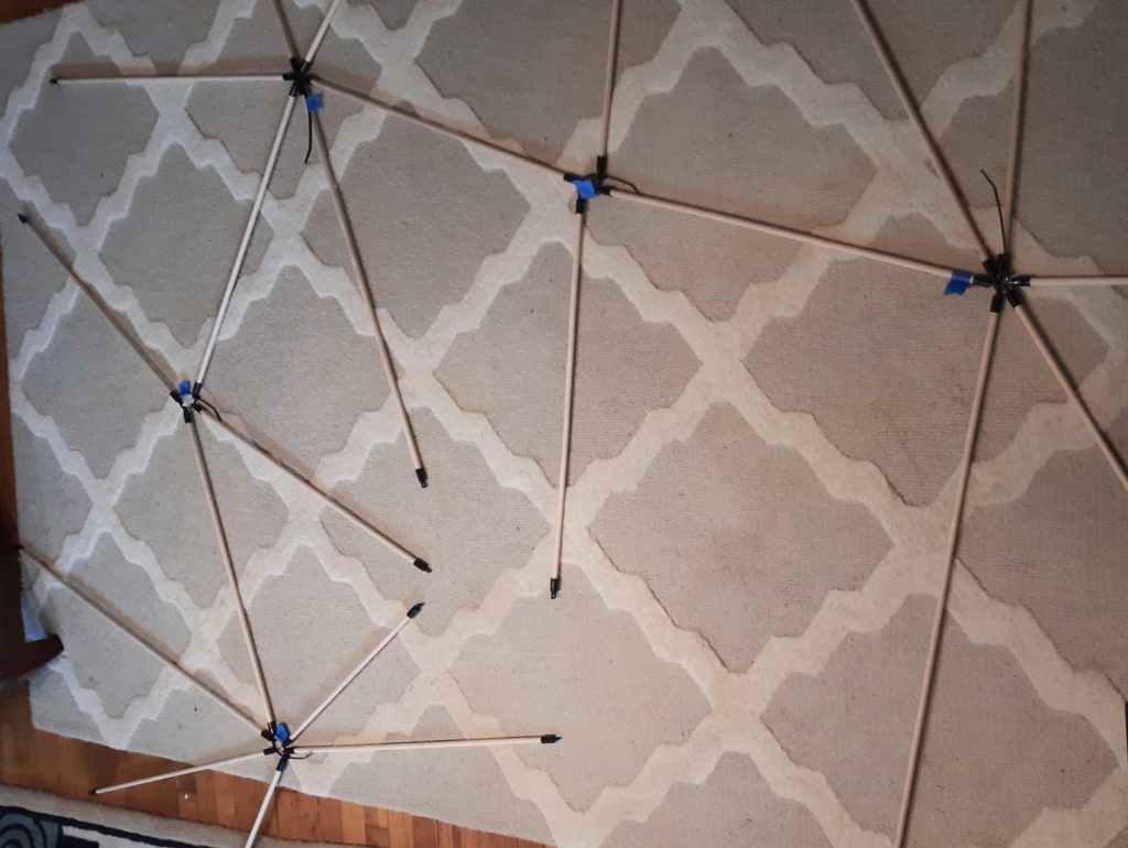
Now by a similar process, you should (6) join the next blue from A clockwise to the blue from vertex D’ between its orange and purple, with two new blues as before, to create vertex D. (Label it!) That gives you the following: (Vertex D is the leftmost labeled one.)
And (7) join the remaining blue from A to the blue-length dowel from vertex E’ between its orange and purple, with two new blues, to create vertex E, like so:
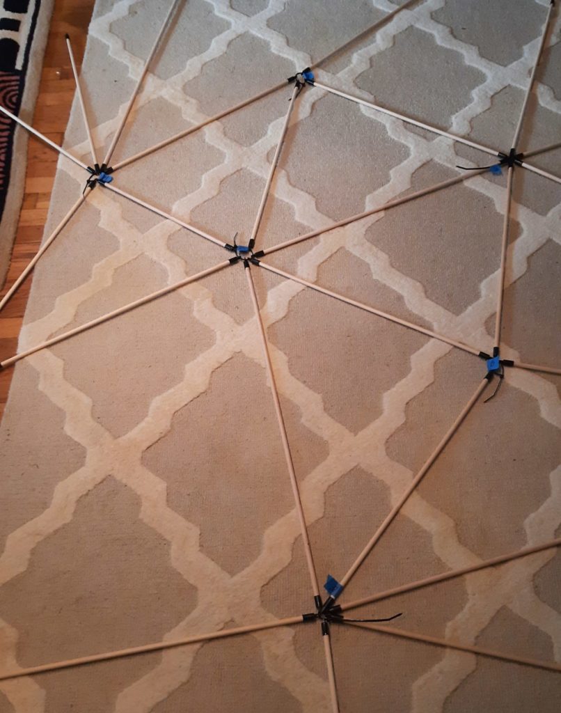
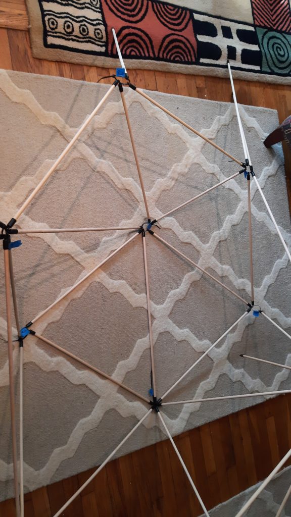
Now if you look back near vertex B that you created in step 5, you should find that the following edges all have free ends near each other in this order: a purple-length one from D’, a blue from D, a green from A, a blue from B, and an orange from B’. So (step 8) lace a cable tie through all of these in order, adding one new blue so that it will end up between the orange and the purple. Close up the tie, pull it partway through, and label that vertex C. Here’s what you get:
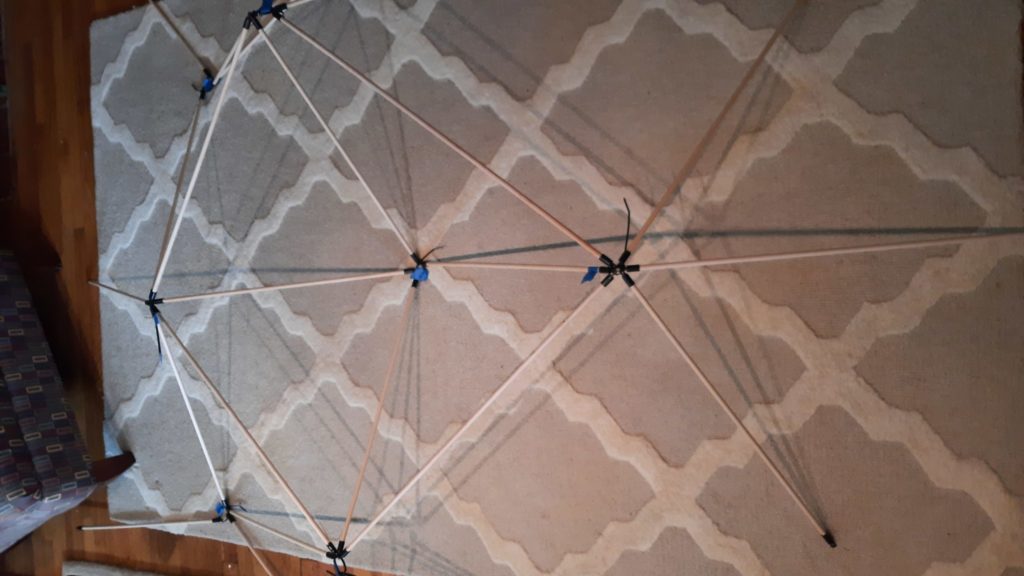
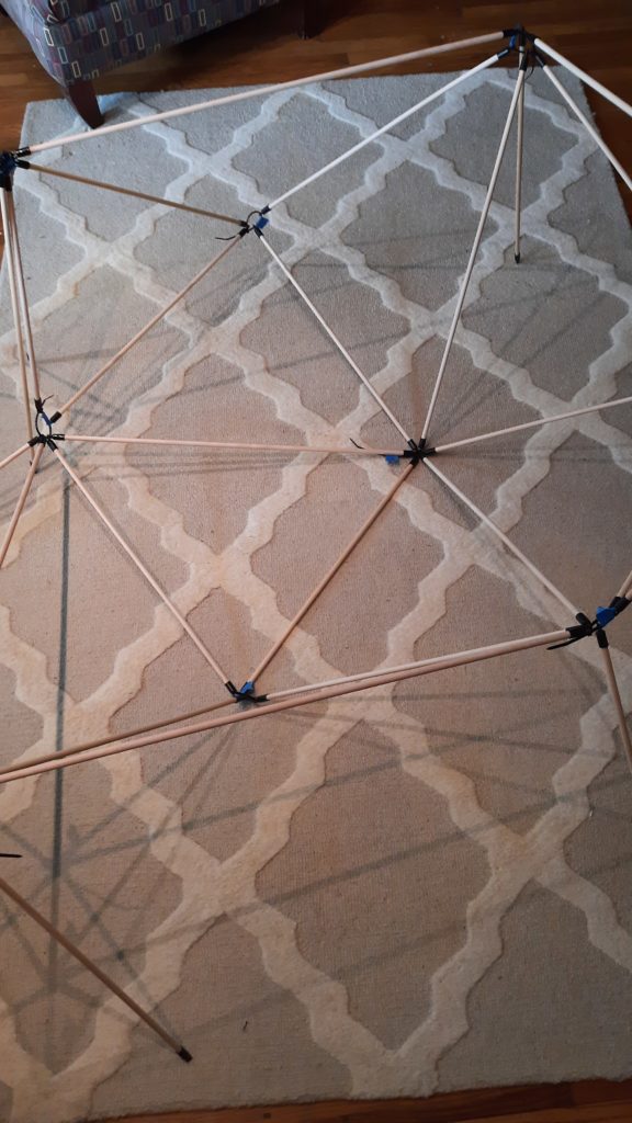
Warning: the next step is the first one in which our partial construction will no longer be able to lie flat on the floor. (Step 9) lace up the purple-length dowel from E’, blue from E, green from A, blue from B, and the other orange from B’ with one new blue-length dowel to create vertex F. You should get something like the following, where the vertex on the floor in the middle is B created in step 5 and the new vertex is at the bottom of the picture:
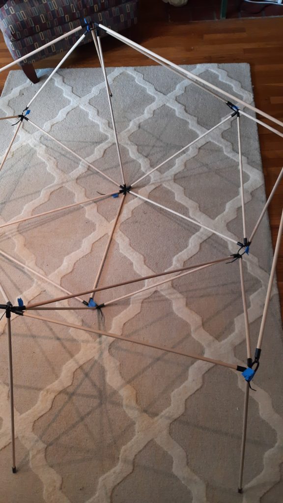
Now we have four more steps, each with just the same format as the last two. So we will list the four steps, and then follow them all by a series of four pictures showing the results after each one. (10) Connect the orange from E’, the blue from E, the last green from A, the last blue from D, and the orange from D’ with one new blue to create vertex G. (11) Connect a blue from B, the last blue from C, and a blue from D’ with one new blue to create vertex C’. (12) Connect a blue from E’, the last blue from F, and the last blue from B’ with one new blue to create vertex F’. (13) Connect the last blues from E’, G, and D’ together with the last unused blue to create vertex G’.
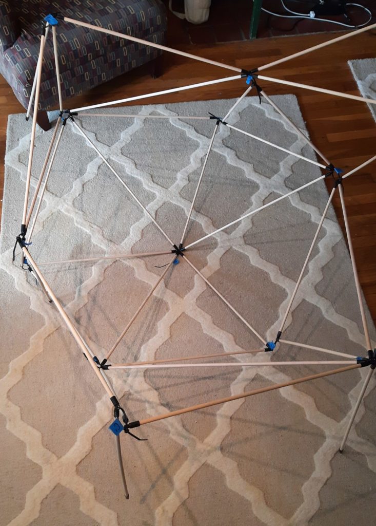
The finale:
And now, you should have exactly 6 free ends — the ones that connect at vertex H. Bring them together and run a cable tie through them. Voilà, you finally have a complete, fully three-dimensional shape. However, it won’t look as crisp as the rendering just yet:
To get there, first check that your structure has the same general shape as shown. If not, back up and try to see where your connections don’t match the ones in the rendering at the top of the post and make any necessary corrections. Once it has taken on an overall shape roughly like a squashed ball, it’s time to tighten it up. Start by picking any vertex and pulling the cable tie there as tight as possible, working to get all of the tabs neatly arranged around the cable tie. Then go to the vertex farthest away from the one you just tightened, and pull that one as tight as possible, keeping the dowels linked to it as neatly arranged as possible as you do. Continue in this same fashion, always switching to the farthest-away vertex that you haven’t yet tightened up, until you have firmly secured every vertex.
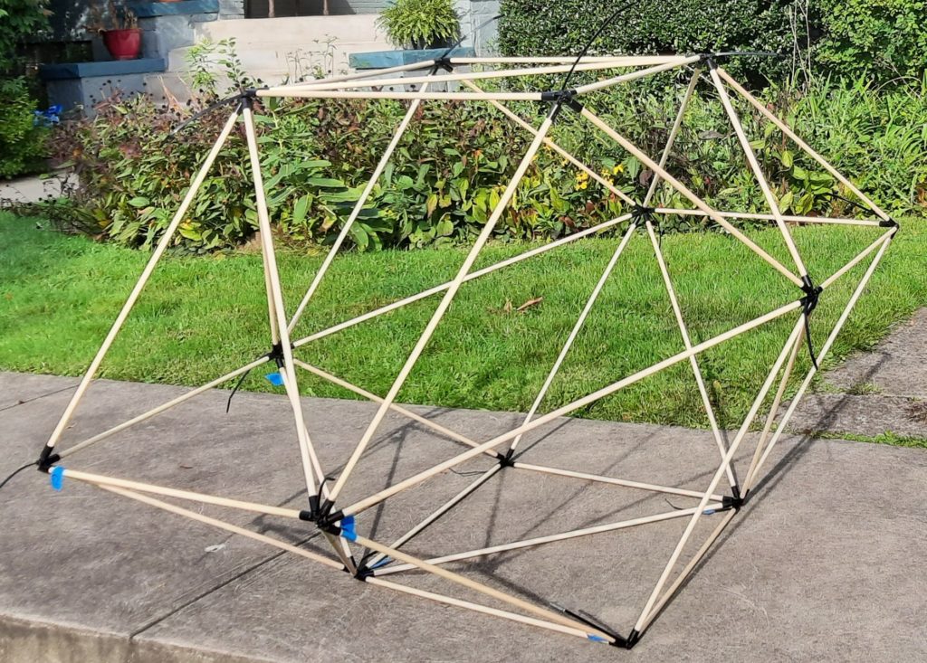
At this point, the structure should have taken on a nice, crisp polyhedral form. You should easily be able to identify the 12 planar rhombic faces, each one split into two congruent isosceles triangles by a diagonal. Here it is in essentially the same orientation as in the initial rendering, but in real life:
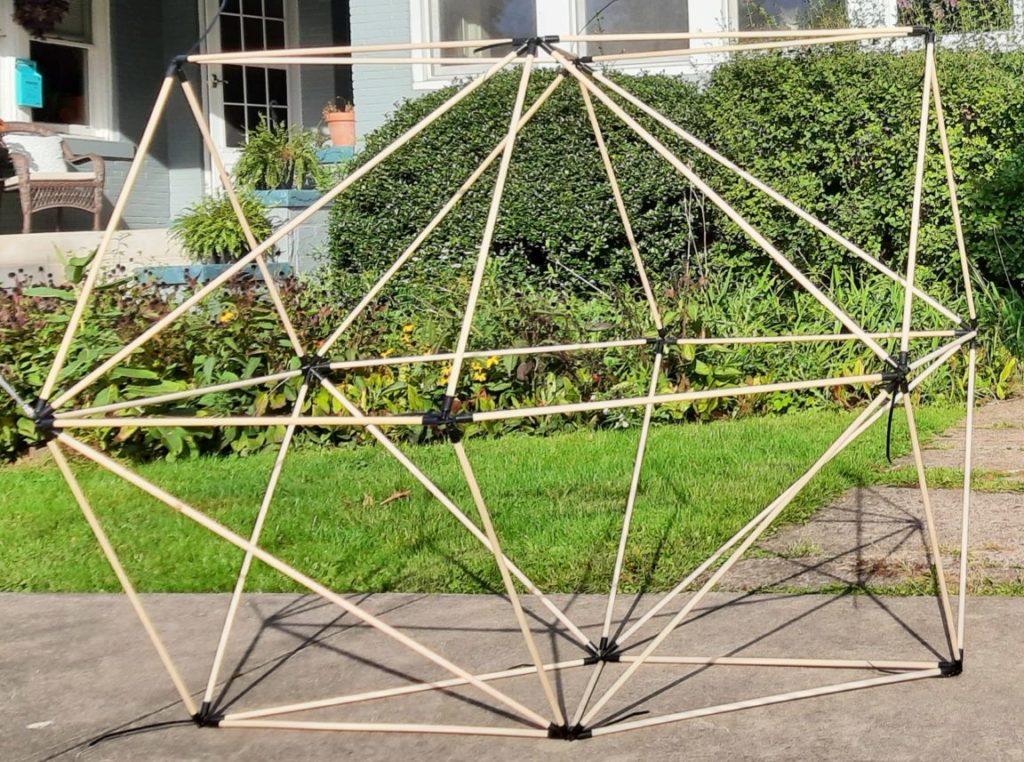
And as a bonus, to get a better sense of the shape, here it is resting on one of its narrow rhombus faces (and with the vertex labels removed):
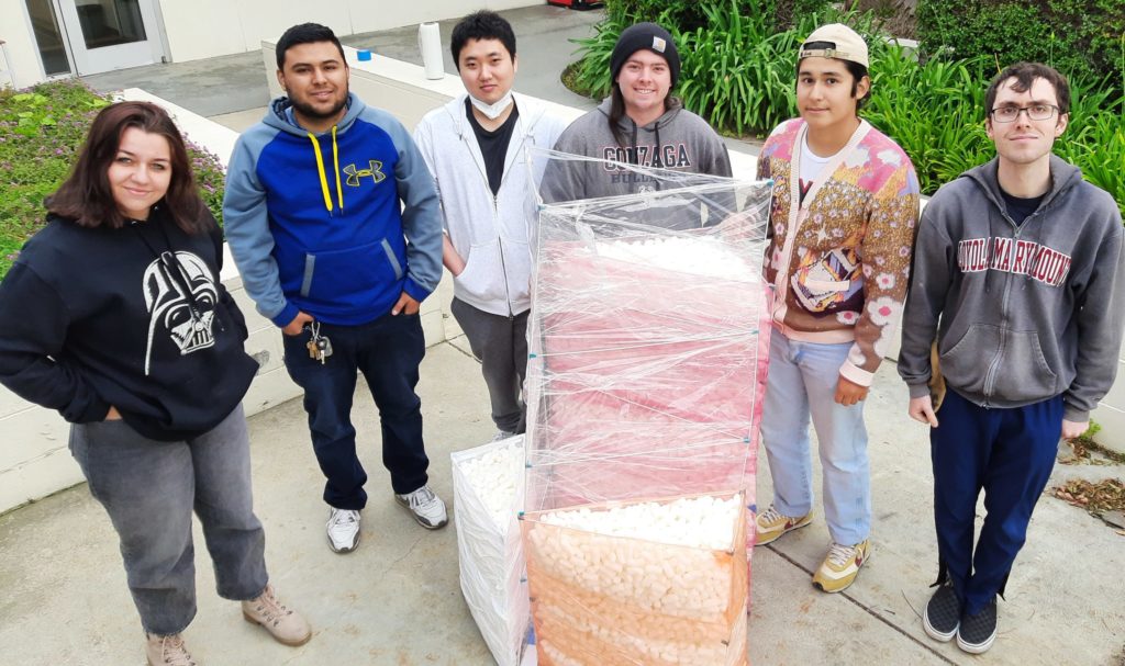
I was recently invited at the last minute to lead a mathematical construction for a seminar for math majors at Loyola Marymount University. The hope was to create something physical connected with one of the topics in the course, which linked the history of mathematics with various unsolved problems, among other things. Since there had been a fair amount of discussion about the Pythagorean Theorem, we settled on the following construction that demonstrates an interesting and less-familiar related phenomenon in three dimensions.
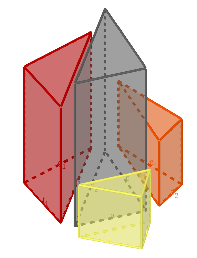
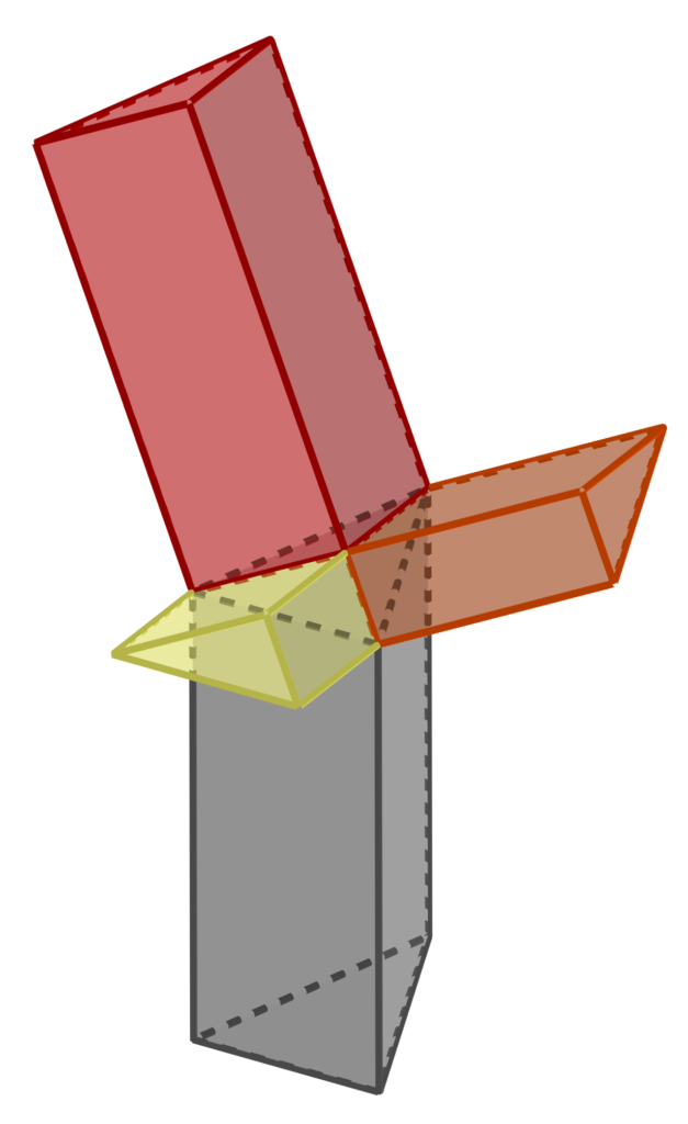
Given any three lengths, you can build a tetrahedron with a vertex where three right angles meet, and the lengths of the three edges meeting there are as given. (Basically, just cut off the positive coordinate axes to the three given lengths and join the resulting endpoints with a triangle.) Such a tetrahedron is called a “right tetrahedron” and those three initial lengths are called the “legs.” The following construction (erecting a prism on each face whose height is the same as the area of the face) can be performed with any lengths for the legs, but all of the calculations below are done for legs √6, √19, and √30 (which have the pleasant property that the sides of the fourth tetrahedron face are then 5, 6, and 7, as shown in the diagram to the right). To create a human-sized result, I used a decimeter as the length unit; if you wanted to make this into a tabletop-sized construction, you could scale it down by a factor of four or five — but note that when scaling down the edge rod lengths (as opposed to the altitude lengths) you need to add one centimeter, divide by your scale factor, and subtract off the one centimeter again, to allow for the extra length created by the connectors.
Materials
Tools
About 30 1/8″ diameter rods, at least 147 cm long (5′ suffices), for example wooden dowels or fiberglass rods
Measuring tape
About 90 custom connector clips (STL file, or OpenSCAD file if you need to tweak them)
Meter sticks
Three sheets of foam core, at least 70 cm by 50 cm (30″ by 20″ suffices)
Cutting pliers or small saw (for cutting rods)
Plastic wrap (ideally four colors of industrial-size rolls)
Box cutter (for foam core)
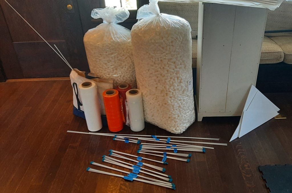
At least 225 liters of loose fill material (e.g. packing peanuts); 9 cu. ft. suffices
Scissors
If rods expand after cuts:
Optional: thick paper or cardstock for temporary lids
Gripping pliers
Drill slightly larger than 1/8″ (e.g. 9/64″)
Assemble all of the needed materials and tools, and fabricate the connectors per the supplied STL file. [vrm360 model_url=”http://studioinfinity.org/wp-content/uploads/2022/04/DowelSnapV6.stl”]
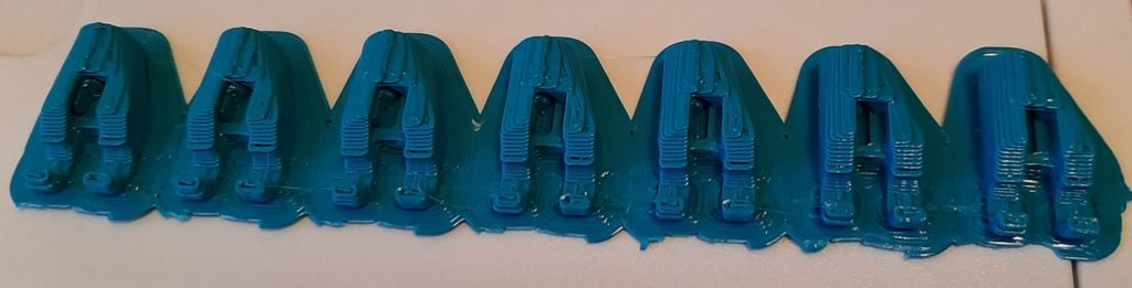
A row of freshly printed connectors before removing the support material
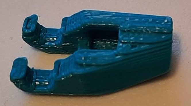
One finished connector ready for use
Length (cm)
Quantity
For
147
3
altitude D
119.4
3
altitude C
69
9
edges of C and D
67.1
3
altitude B
59
8
edges of B and D
53.8
7
edges of B and C
53.4
3
altitude A
49
8
edges of A and D
42.6
6
edges of A and C
23.5
6
edges of A and B
Then begin by cutting lengths of your edge rods as in the table to the right:
Because the vendor-supplied cut ends of the edge material will likely be more uniform than your hand-made cuts, especially if you choose to use cutting pliers, try to preserve as many of the manufactured ends as possible when cutting.
Next, slide connectors onto both ends of each of the rods designated for “edges” in the table above. With the fiberglass rods I was using, the ends I hand-cut with pliers deformed and expanded, so I had to ream the holes of the connectors for these ends out to 9/64 inch by hand-twisting a drill (held by gripping pliers) into the holes.
Cut a foam-core bottom for each of the prisms, corresponding to the four faces of the central tetrahedron: the largest face D has edges 50, 60, and 70 centimeters (I just measured off 70 cm along one edge of a foam-core sheet, and then laid meter sticks down so that their corners met and they read off 50 and 60 cm respectively at the corner and marked point on the edge). The other three faces A, B, and C (in order of increasing area) are all right triangles, so I just measured the leg lengths along two adjacent sides of a sheet and then cut the resulting corner piece off. The lengths are: A – 24.5 and 43.6 cm, B – 24.5 and 54.8 cm, and C – 43.6 cm and 54.8 cm. (Note the edge lengths of the foam core faces are all 1 cm greater than the corresponding edge rods, because the connectors at each end of a rod add exactly 1 cm to their effective length.)
Assemble each of the prisms by clipping edges onto altitudes to form the desired cross section.
Every prism should have a triangle of edges at each end of the altitude, and at least one additional group of edges around its middle; the quantities above have been set so that the tallest prism D can have three internal sets of cross braces and B can have two. One set of cross braces at mid-height for prisms A and B seemed to be plenty. Note that the clips can interleave at the ends to produce triangles with coplanar rods, except for the two most acute angles (the sharpest angles of triangles A and B), where you will have to place them side by side. You can actually get a bit more stability on the taller prisms by staggering the interior cross braces slightly, rather than making each set coplanar. But on all of the prisms, the cross braces at the ends should be as close to coplanar as possible.
When you have made all the prism frameworks, attach the foam core bottoms to each prism with tape. For the finale, it matters a bit which end of each prism you attach the bottom to, and this is an aspect that was unfortunately not done correctly in the pictured build. The easiest way to get it right is to stand the D prism in the center, and then line up the A, B, and C prisms with their hypotenuses matching with the sides of prism D. Orient A, B, and C so that the legs of adjacent prisms match in length (see the diagram at left). Then attach the bottoms.
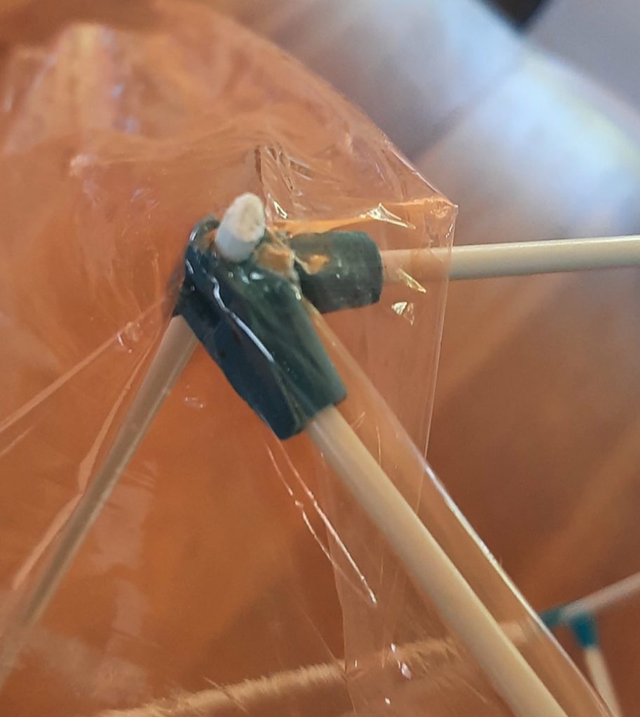
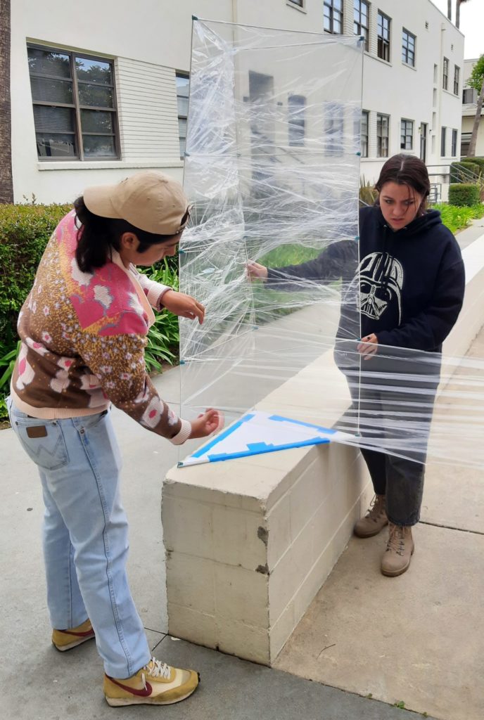
The last step in preparing for the finale is to add vertical sides to your prisms. This could be done with any sheet material (you could cut rectangles to size) but the quickest and easiest way, that also allows you to easily see what’s going on in the finale, is to wrap them with cling wrap. Industrial packaging wrap is readily available in a variety of colors, or you can use ordinary consumer food wrap (although you will likely need an entire roll). Begin the wrapping at the top by hooking the wrap onto one of the altitudes (see photo at right), and then leaving some extra wrap above the top crossbars, make one circuit of the triangular perimeter. Fold the extra down around the top crossbars, and then continue to wrap around the prism angling downward somewhat so that at least half the sheet overlaps with what’s already there at all times. Continue past the bottom panel of the prism, and then fold the excess underneath and secure with tape or by stretching and sticking the wrap to itself. The process and results are depicted below:
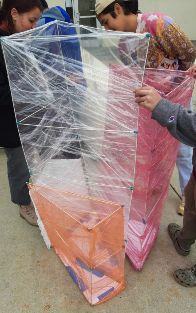
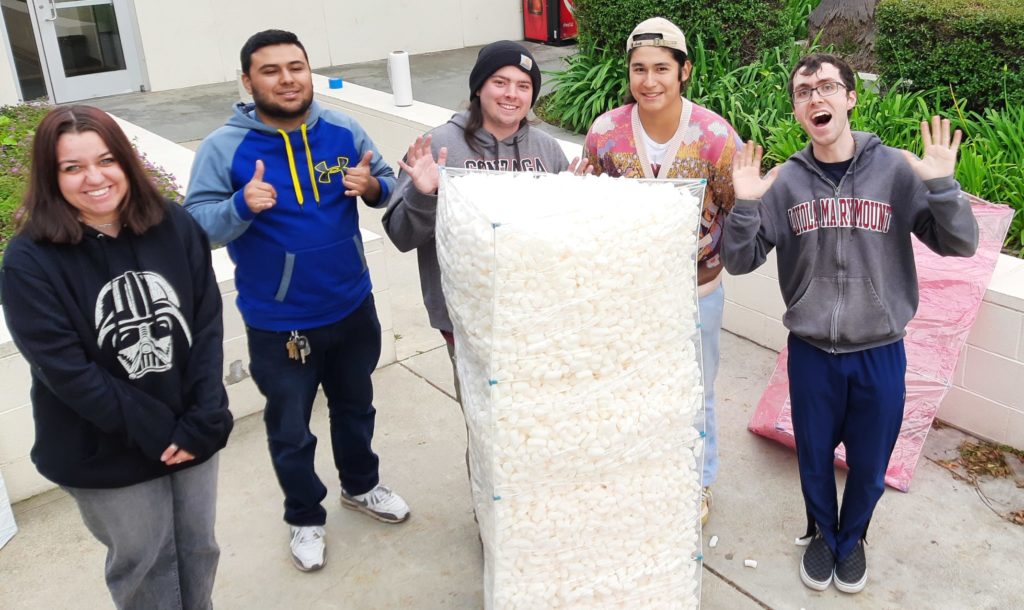
Once all of the prisms are wrapped, it’s time for the finale. Fill the three smaller prisms A, B, and C with loose, light filler material — we used water-soluble “packing peanuts.”
Ideally, if the bottoms are placed on the proper sides, you can now place loose temporary lids on top of prisms A, B, C, and invert them above prism D to create a space congruent to the right tetrahedron above prism D, showing the prisms of height equal to face area erected on all four faces of the tetrahedron. (See diagram at left for how that might look.) Then pull the temporary lids out and allow all of the filler material to tumble down into prism D.
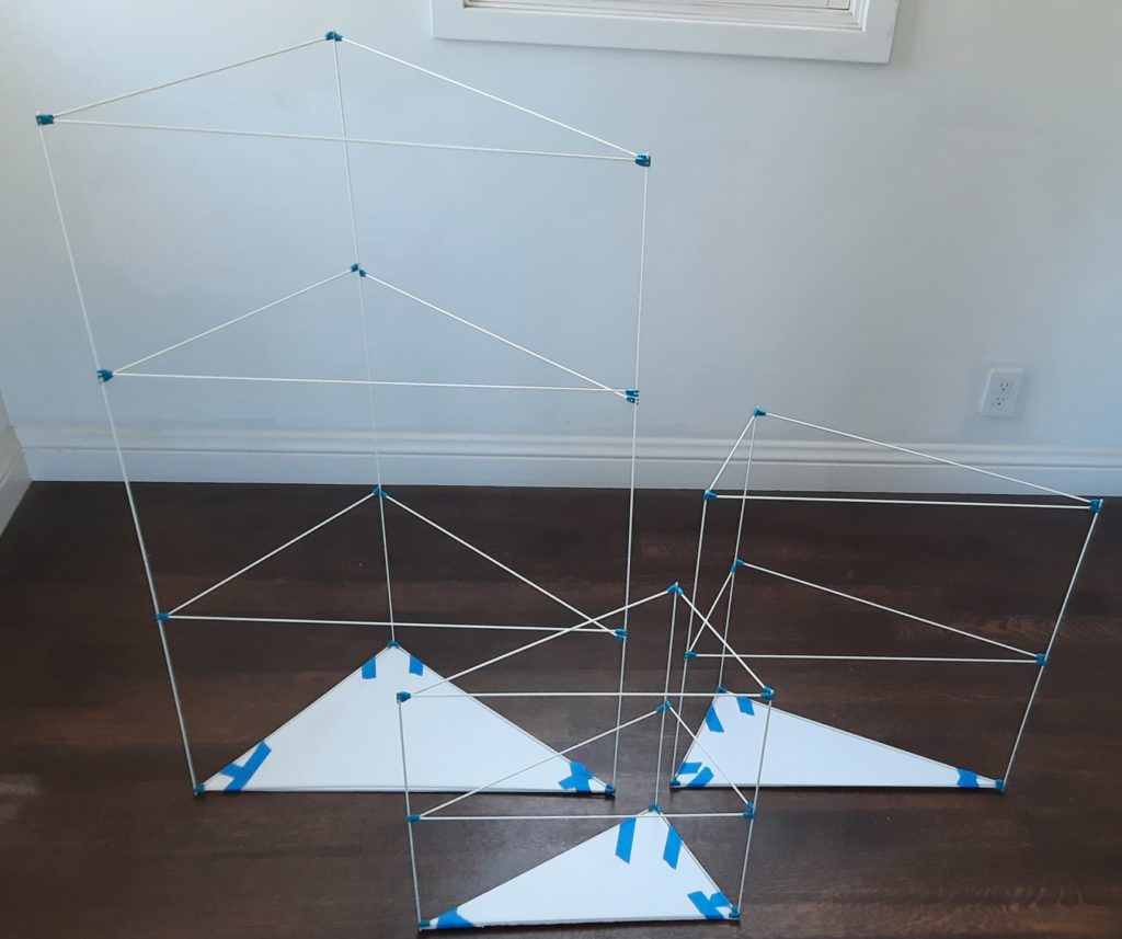
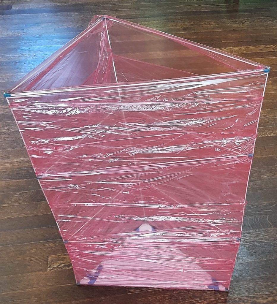
If that’s too complicated or the bottom panels were not on the correct ends, simply dump all of the contents of A, B, and C in turn into prism D (as depicted to right). Here’s what you get when you’re done:
And voilà — the material exactly fills the largest prism D! Is this a coincidence? Seeing as how this is Studio Infinity, of course not. What are the volumes of these prisms? Well, letting A, B, C, and D also stand for the areas of the four faces, we have the height of prism A is also A, and so on through the height of prism D is D. And since the volume of a prism is the area of its base times its height, the volumes of the prisms are A2, B2, C2, and D2. And it turns out that for any right tetrahedron, A2 + B2 + C2 = D2 — this is the Three-D Pythagorean Theorem. So the big prism was guaranteed to fill up exactly!
With all of the recent activity at Studio Infinity on geometric units that can be automatically cut and scored, it was natural for the S∞ G4G14 giveaway to be the 14-sided Truncated Octahedron, which tessellates to fill space. The additional challenge here as compared to some of the earlier interlocking structures was to ensure that the resulting polyhedral units would be able to connect arbitrarily face-to-face, so that it’s possible to explore the three-dimensional structures you can build with multiple truncated octahedra.
This was accomplished by two measures. First, by leaving the square faces empty (fortunately the truncated octahedron is still rigid with its square faces deleted) and putting connection tabs similar to ITSPHUN units on the corresponding edges. That step allows any square face to connect to any other square face, in any of the four possible orientations.
Second, I cut out a triangle (not a hexagon!) from the center of each hexagonal face, and added similar connection tabs to those. That allows any hexagonal face to connect with any other hexagonal face, but only in the three orientations that allow the space-filling tessellation to continue.
These ideas result in the following SVG template:
The black lines are cuts and the magenta dashed lines are scores (all for mountain folds). If you are cutting directly from this SVG, you can also cut just the dashes of the magenta lines on very low pressure/high speed to create scores that fold well.There are two units because it takes two to create a single truncated octahedron, and to illustrate how they interleave for cutting, leaving very little unused material. (The outermost protruding tabs are for connecting these two pieces into one polyhedral unit.) In case it’s helpful, here are a PDF and the DXF design file for this unit.
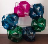
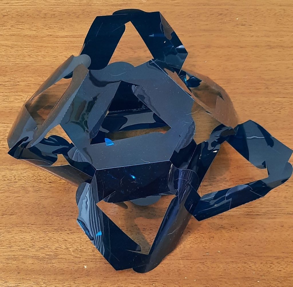
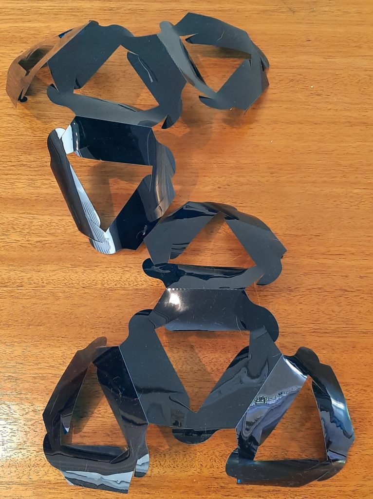
See the previous post for full assembly instructions. I’ll leave you with an image of the smallest loop one can make, with six completed units.
If you build an interesting structure with these units, please post a picture in the comments!
These are the assembly instructions for the Tessellating Truncated Octahedra; you’ll find background and the cut files for them on them in the following post.
Materials
Two TTO pieces per unit you wish to build
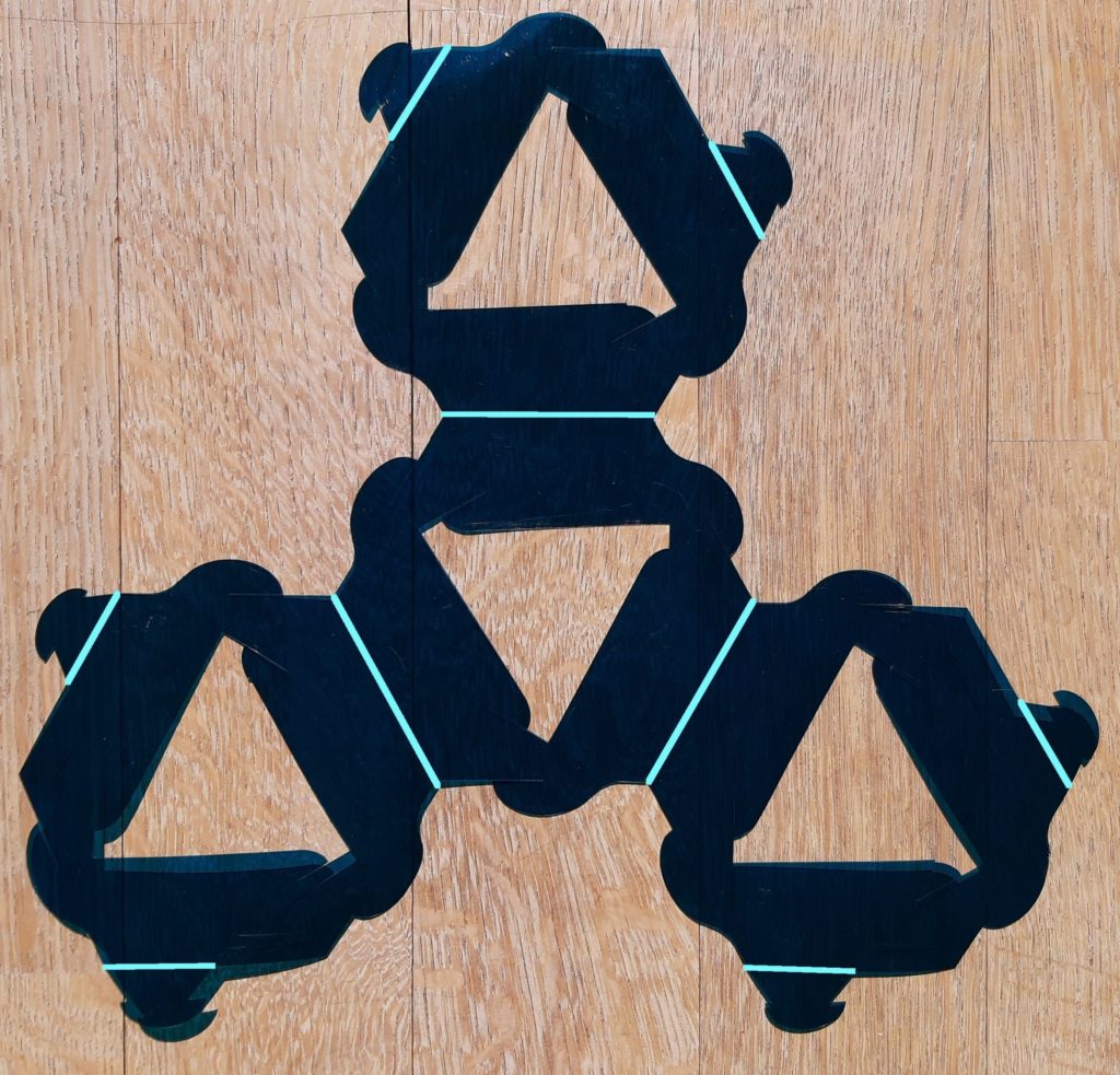
The first order of business is to fully cut and punch out two of the pieces from the cut templates in the following post, including removing the triangular inserts in the four hexagonal faces, and separating all of the tabs and slots. That will produce a piece that looks like the following picture (with the score lines in the template highlighted by light blue lines, as otherwise they are difficult to see in the photograph):
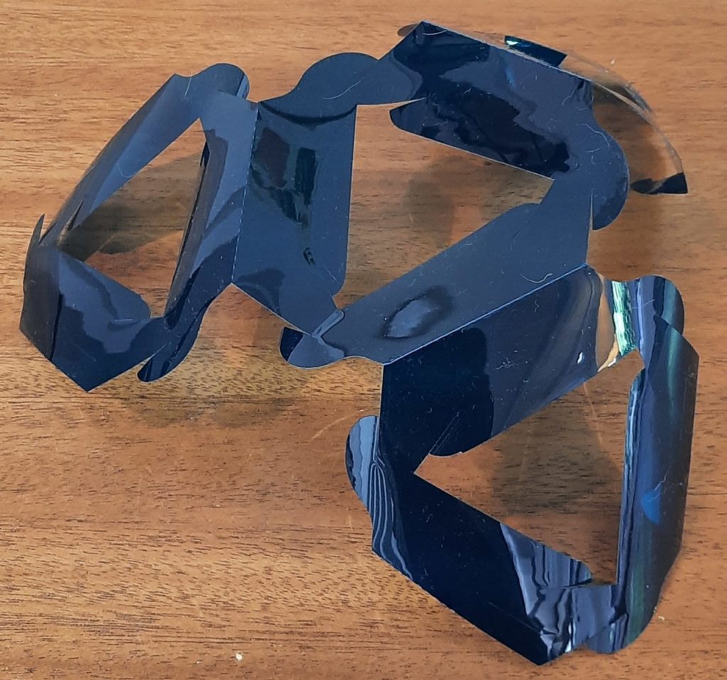
Now make a mountain fold on each of the score lines, producing something that looks like this:
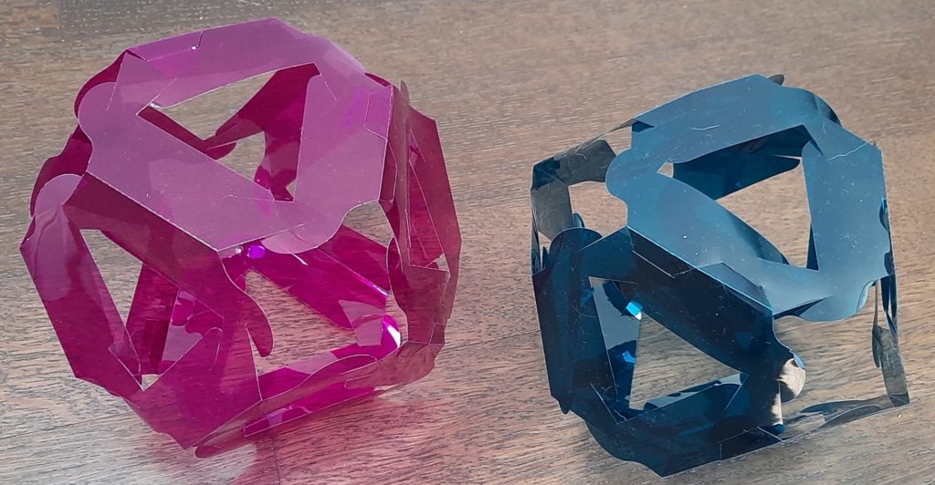
Repeat with another piece. Two of them will interlock to produce a single truncated octahedron unit. The picture on the left below shows them overlapped in roughly the relationship they will have when connected; the picture on the right shows two of the edges lined up ready to be connected.
To connect this edge, start inserting the long flap of one of the tabs on that edge into the slit opposite it on the other piece, then pull that tab all the way in, then repeat with the other tab along that edge (on the piece that has the slit in the first part of the connection, going into a slit on the piece that had the tab). This process is shown in the following sequence of three photos:
Now work your way around the unit, connecting six edges in all. The left photo below shows me working on the second edge, and the right photo shows the state with three edges connected.
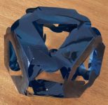
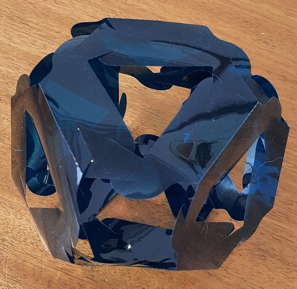
When you’ve done all six edges, you’ve completed your first truncated octahedron unit, which looks like this:
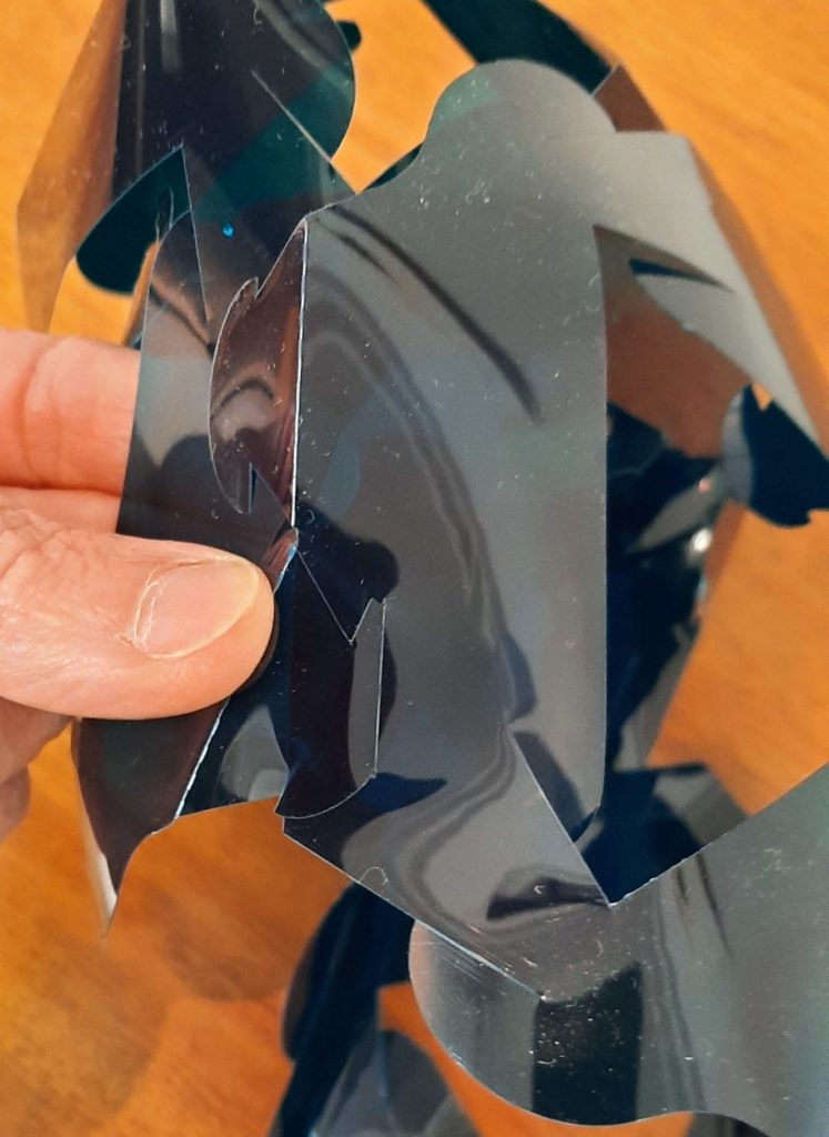
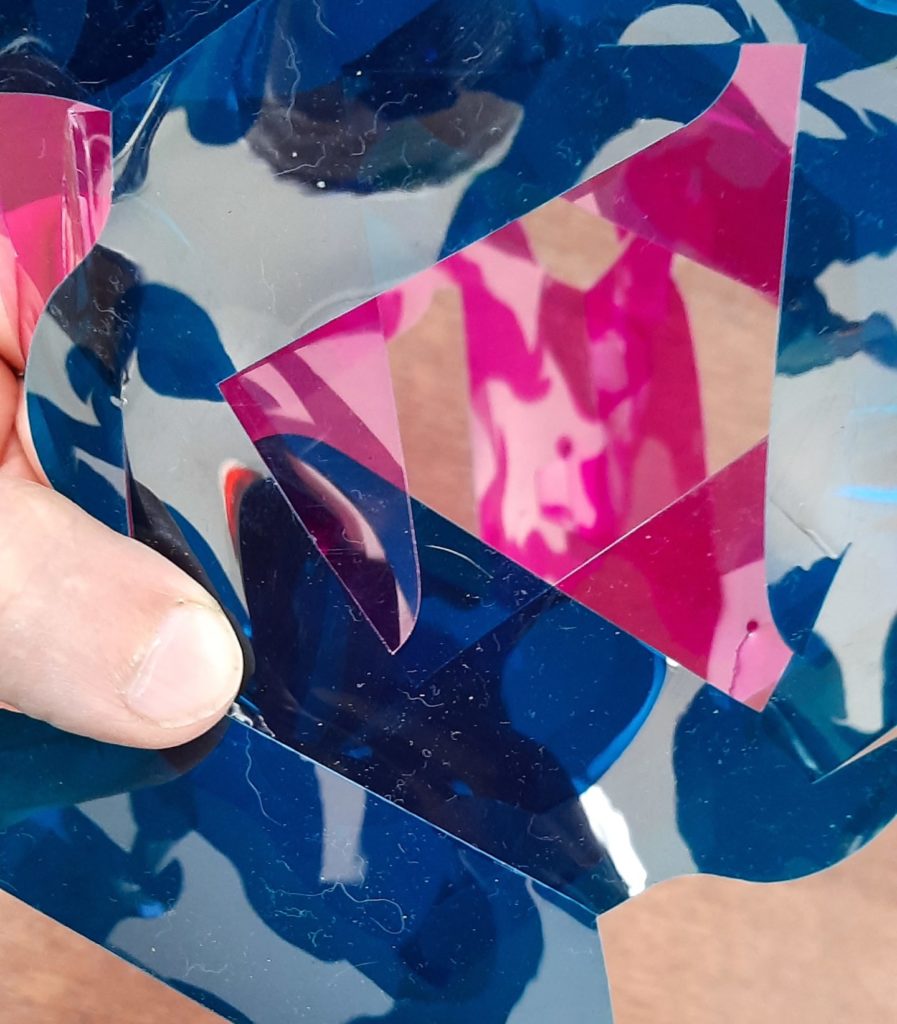
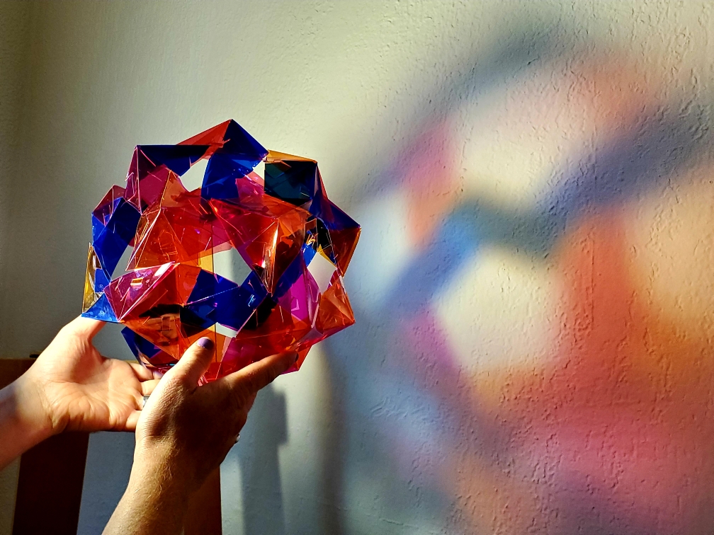
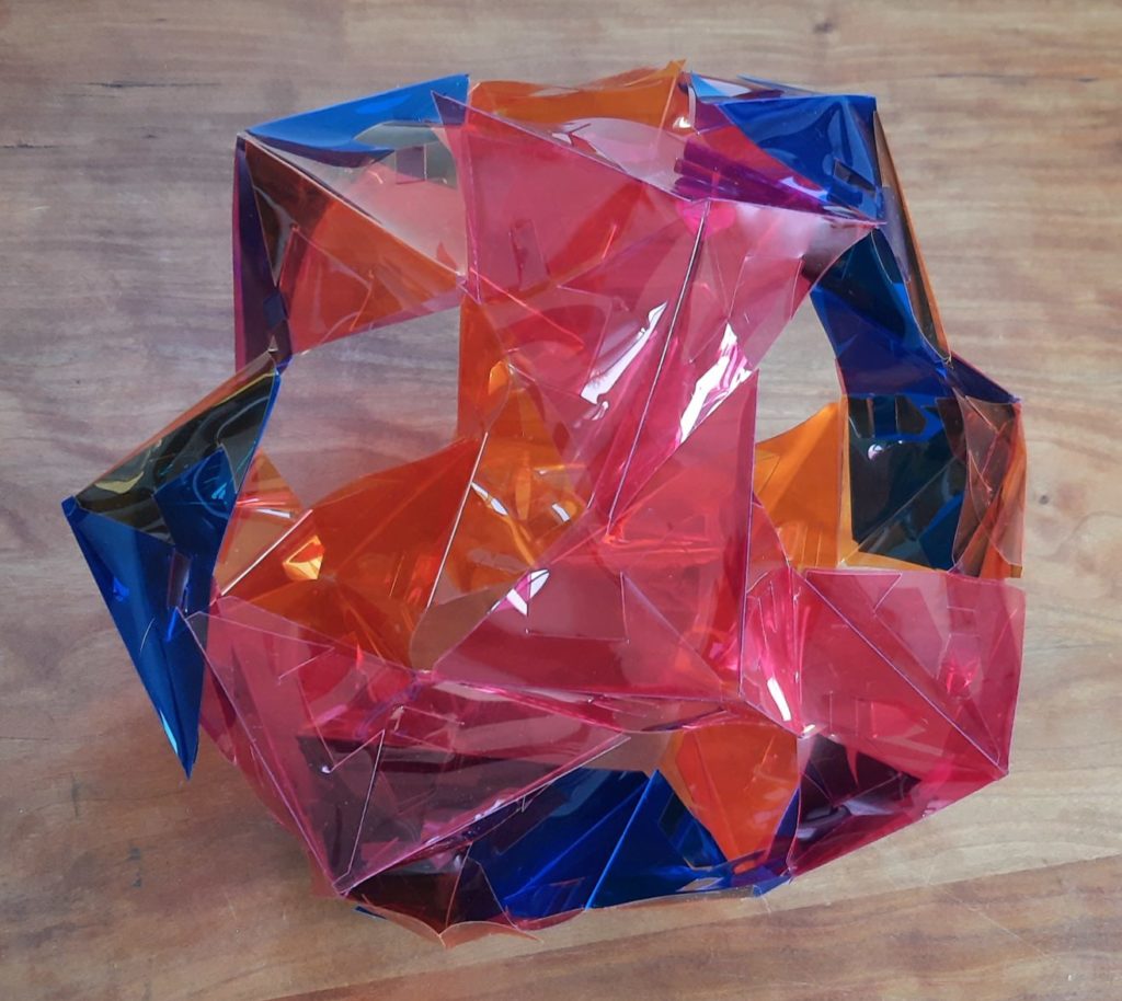
But the distinctive thing about these truncated octahedra units is that they can connect arbitrarily face to face in their tessellation of space. Connecting square faces (which are empty in each individual unit) is relatively straightforward: just line up their edges however you’d like and engage the four pairs of corresponding (but opposite-pointing) edges. Connecting the hexagonal faces is just slightly trickier, because they line up in the tessellation in only three (not six) ways. (The other three ways would force two square edges to be adjacent; but as each TO unit does not have any adjacent square edges, that can’t happen in the tessellation.) So you have to line up two units so that the tabs in their triangular cutouts will engage, like so:
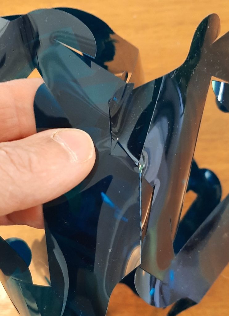
Then line the corresponding faces up with each other and engage the three tabs around the triangular cutouts. (You may have to bend the tabs back pretty far to get them past each other to engage, so hopefully you’ve cut your pieces out of a sufficiently flexible material, like this plastic — Roscolene lighting gel, to be exact — paper and cardstock will also work fine if you’re OK with opaque units.) Here’s me having just connected one pair of tabs around a triangular opening:
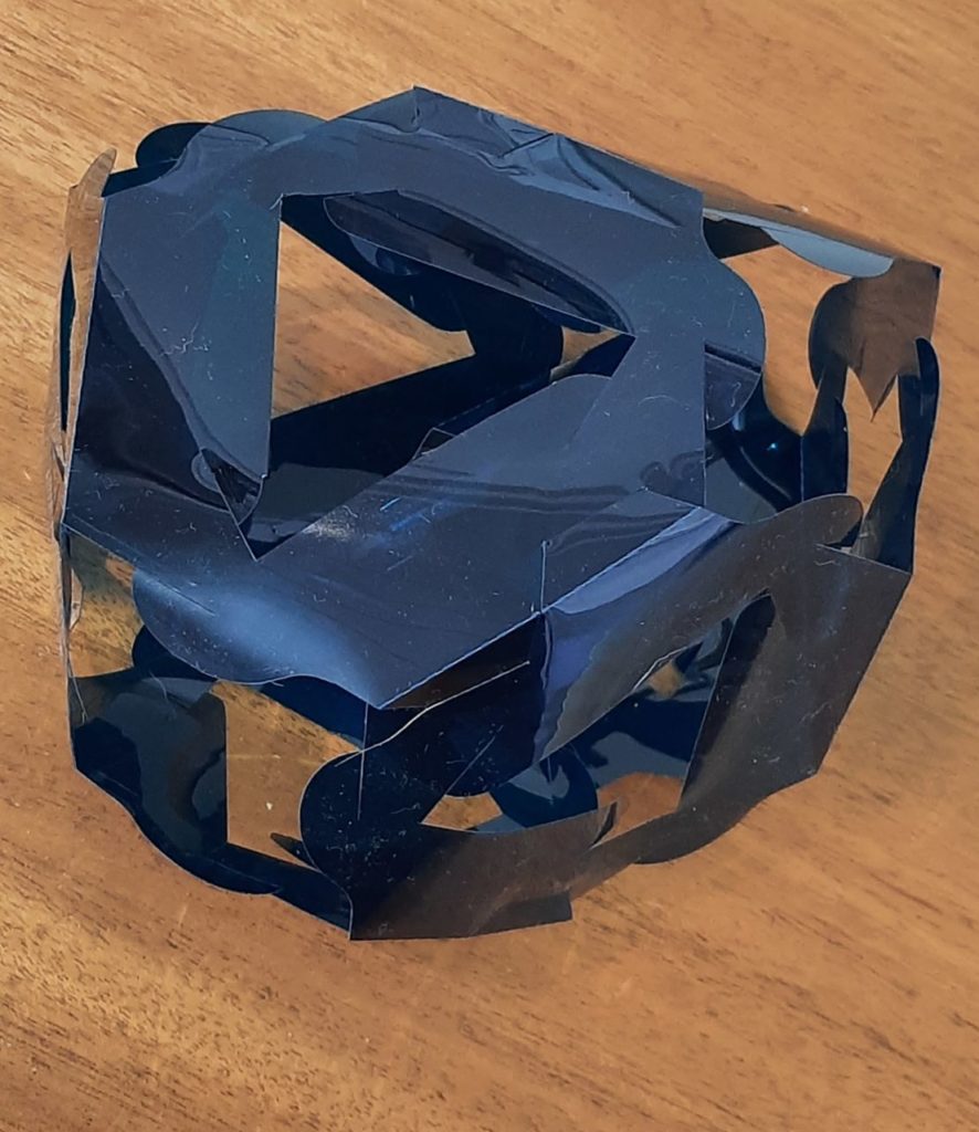
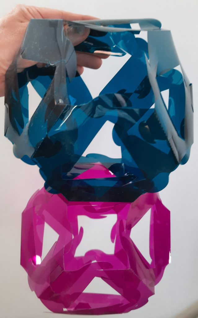
Once all three pairs of tabs are engaged, you’ll find the connection to be quite robust:
Enjoy assembling and connecting your Tessellating Truncated Octahedra! What kinds of loops, bridges, and shapes can you build?
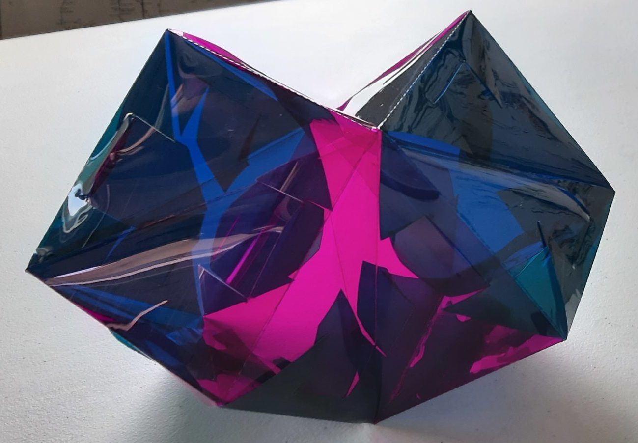
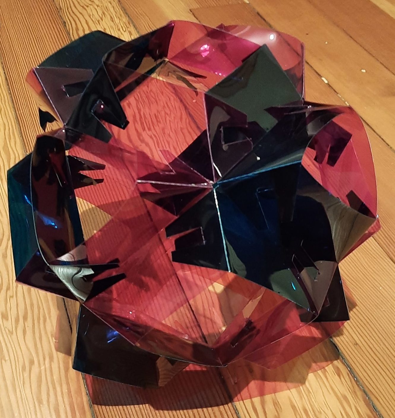
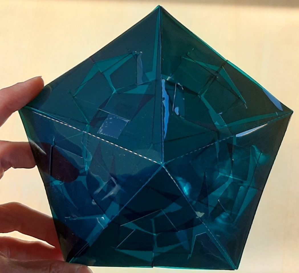
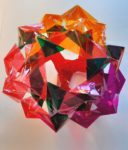
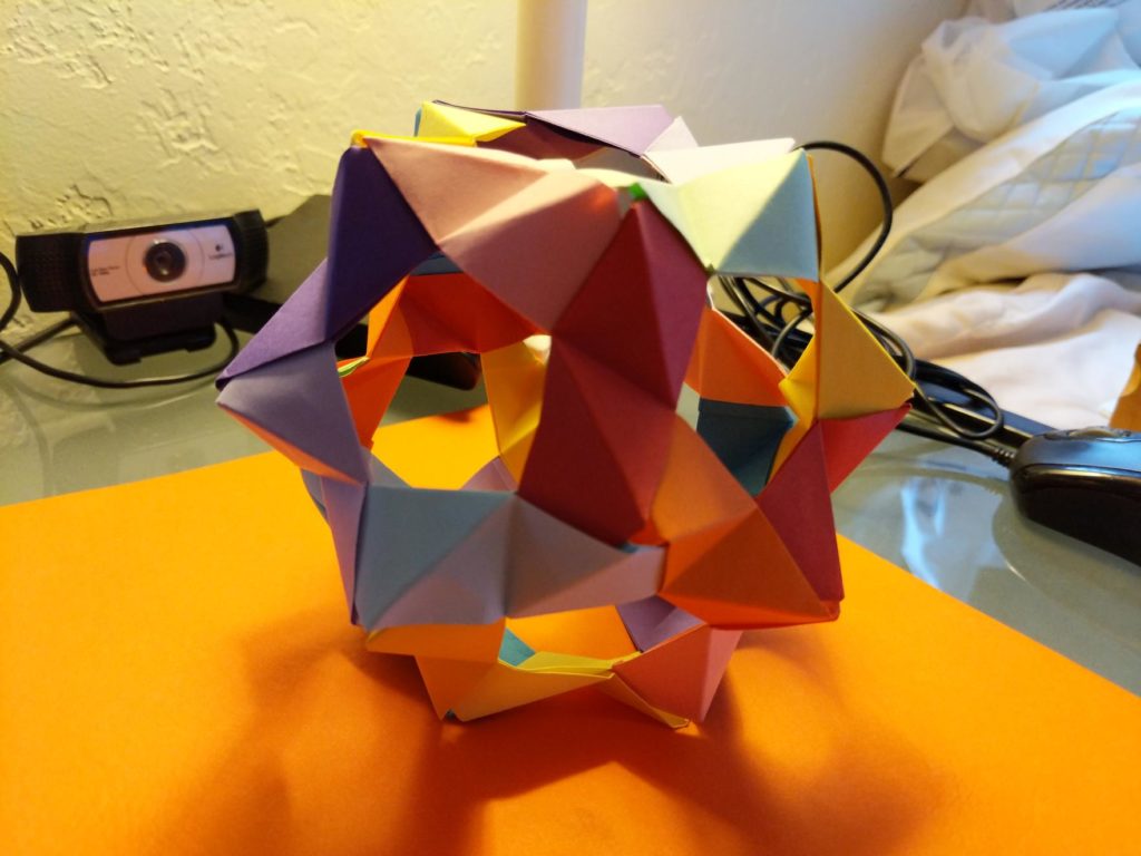
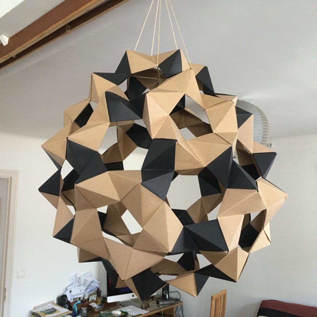
Another aspect of the PCMI session on Illustrating Math was a series of exploratory, hands-on workshops. One of them focused, in part, on the design of modules like the one for the truncated triakis tetrahedron, but based on other existing modular origami units.
It’s more or less possible to transpose any modular origami unit to a cut-and-score single-sheet module with tabs and slits, as the following table of designs from the workshop shows:
A key difference that emerged from these workshop examples as compared to the PHiZZ units is that this plastic sheet material produced beautiful results on these geometrically exact units, whereas it did not distribute the slight geometric imprecisions inherent in PHiZZ unit constructions nearly as well as paper units do. (Many of the modular plastic PHiZZ constructions end up looking slightly lopsided, whereas the models from the workshop were all extremely crisp.) This distinction definitely plays into future material selection for geometric constructions.
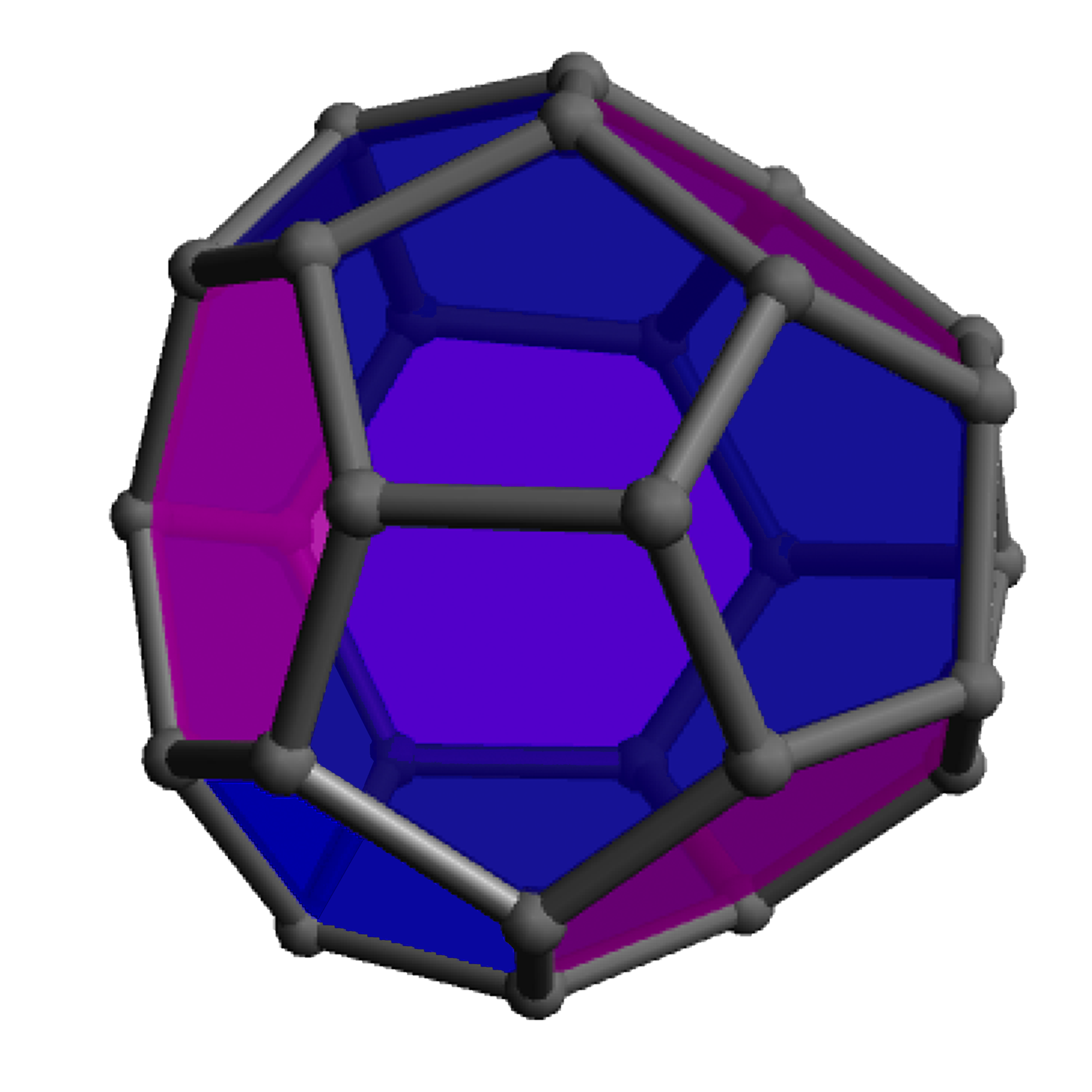
For the actual building event mentioned in the previous post (linked above), participants could choose from a variety of target polyhedra. The origami inspiration was the PHiZZ unit, which stands for Pentgons Hexagons in Zig Zag, so the ideal targets consist of just pentagons and hexagons. With Euler’s formula for polyhedra and a little calculation you can determine that such a shape must have exactly twelve pentagons and almost any number of hexagons; the page for the event includes a table of candidates.
I chose the Truncated Triakis Tetrahedron as my target: (not only because of the alliteration, it’s a nice size and has pleasing symmetry that breaks the building down into four simple, identical sub-assemblies)
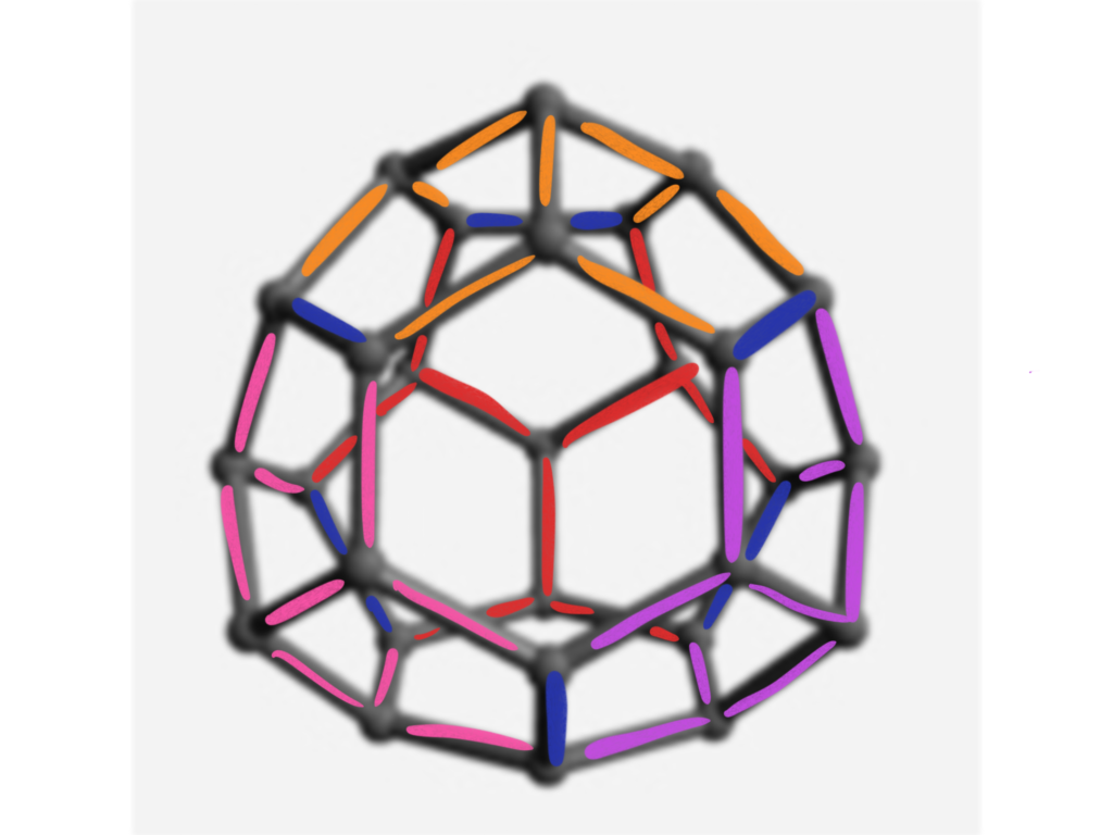
To assemble this, I worked from a diagram of the edges, graciously colorized by Elliot Kienzle:
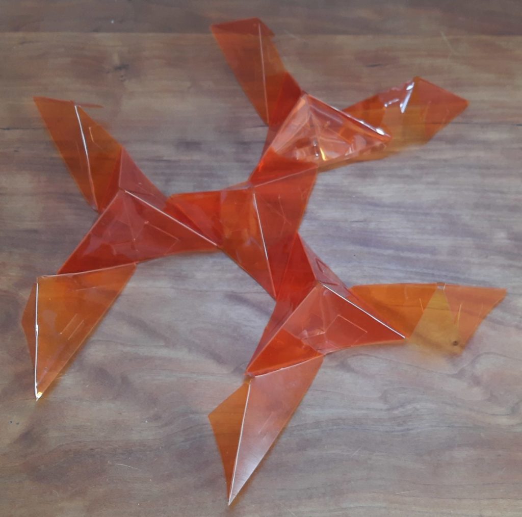
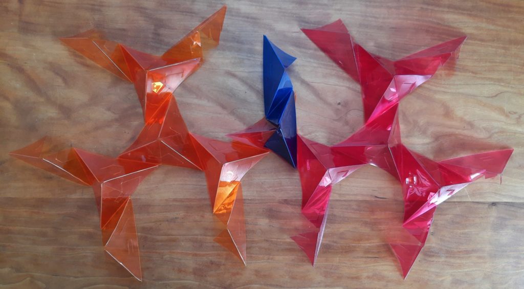
I found it easiest to start by making each of the lighter-colored sections. They’re all the same, made of nine pieces each. You make one three-way connection all the same color (as shown in the previous post), and then turn each of the three opposite ends of each of these pieces into a three-way connection, like so:
Repeat with the other three colors.
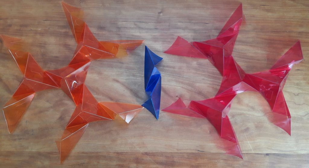
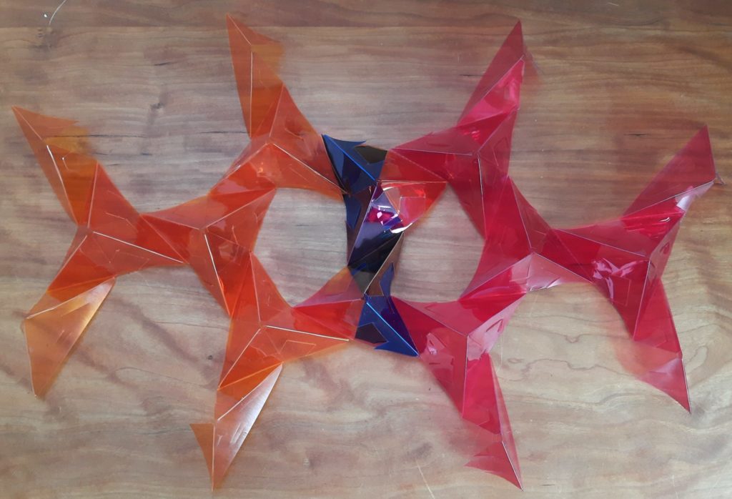
When you have your four sub-assemblies, you can connect two neighboring loose ends of one color with corresponding loose ends of another color at the two ends of a new unit of the darker color. Here are the components laid out schematically to show how they go together:
And here they are overlapped in the actual way the first trio of connections will be made:
And here they are once both ends of the blue unit have been fully connected:
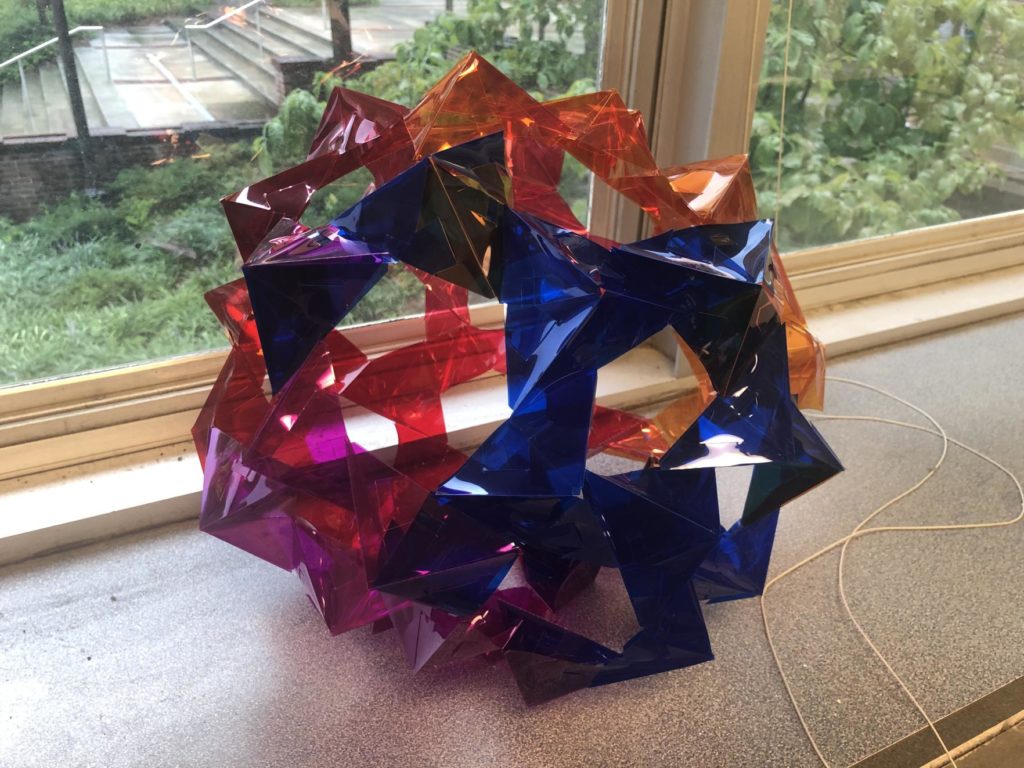
This process of connecting sub-assemblies with one additional unit happens in six places, shown by the blue edges in Elliot’s diagram above. (These six edges are actually the remnants of the six original edges of the tetrahedron that the truncated triakis tetrahedron is based on.) Once you’ve made all those links, everything hangs together like so:
(Note that this image is shown from the same perspective as Elliott’s diagram above, used as the construction guide.)
Participants took this basic concept in a variety of directions, and here’s a mini-gallery of some of the results:
Emily Z
Katherine Booth (75 edges!)
Kate Stange
Rémi Coulon
Gabriel Dorfsman-Hopkins
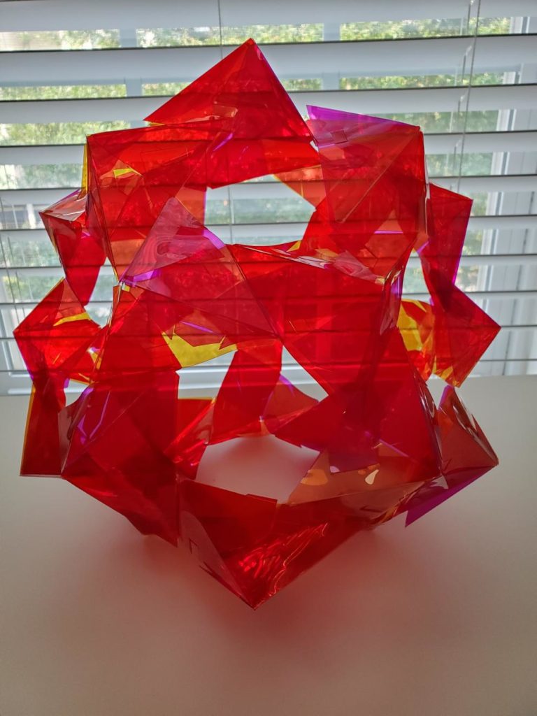
As a final bonus, the units are flexible enough so that you can break the pentagon/hexagon only rule: this shape is made by connecting just two of the truncated triakis tetrahedron sub-assemblies to each other in all three possible places, and it contains three quadrilaterals and six pentagons.