An irregular rhombic dodecahedron
I will be leading a group construction of a 3.4m diameter rhombic enneacontahedron next Tuesday, 2022 Oct 11, on the campus of Dickinson College. This is the first time that I will be leading a construction using this system — dubbed ZipStix at the NYC math museum — with rhombic faces rather than regular polygons.
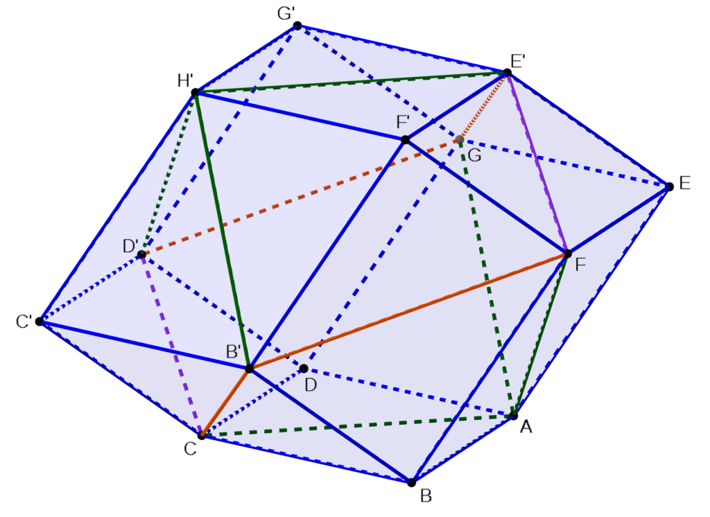
So to prepare, last weekend I built the prototype you see in the diagram at right. It has twelve faces (hence the post title) and uses both of the rhombus shapes that appear in the enneacontahedron, as well as a third rhombus that is almost, but not quite, a square. Here are the complete build instructions.
| Materials | Tools |
|---|---|
| 24 wood dowels, 2′ long by 3/8″ diameter | small handsaw for cutting dowels |
| Enough additional dowels (e.g., 11 dowels 3′ by 3/8″) to cut the following lengths: | light hammer for tapping caps onto dowels |
| 4 dowels 32 3/4″ long, 6 dowels 27 3/4″ long, and 2 dowels 17 1/8″ long | (optionally) angle brackets for backing up caps when tapping |
| 72 plastic end caps for 3/8″ diameter dowels, similar to these | (optionally) instant-setting glue for caps that slide off during construction |
| 14 “zip-style” cable ties | easily-removable tape (like painter’s tape) and markers for labeling parts during construction |
First, measure the lengths of all the dowels you need to cut. Here’s one of the 17 1/8″ dowels being measured (you can get two of these from opposite ends of one 3′ stock dowel), and below that, all of the 27 3/4″ dowels ready for cutting.


Next, cut the dowels to the marked lengths, and insert each end of each dowel into an end cap. Depending on the tolerances of the end caps and the dowels, you may be able to do this by pushing the caps on firmly by hand, or you may need to tap them on with a light hammer. In the latter case, you probably need to brace the caps against something to avoid breaking the tabs on the plastic caps. So place a right-angle bracket that is at least as wide as the tab is long on a flat work surface (so that the right angle is against the table), place a cap with a partially-inserted dowel so that the flat part of the cap at the end of the tab is against one arm of the bracket, and tap the other end of the dowel. To get the second cap on, first make sure that the two caps are roughly “lined up” so that their tabs are more or less in the same plane. Then, you will likely need to hold another bracket against the end cap at the other end of the dowel to have a surface you can tap on (watch your fingers!).
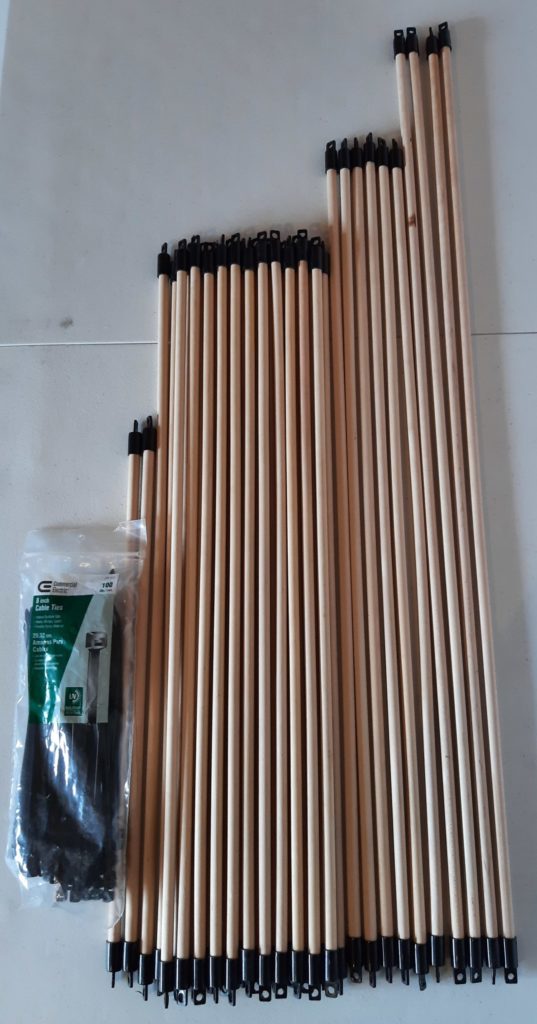
At left you can see all of the dowels cut, capped, and ready to go, together with the bag of cable ties we’re going to use. The assembly will proceed from vertex to vertex in the diagram above — you probably want to print out a copy to be able to refer back to it as you go through the construction process. The edges (dowels) in the diagram are color coded by length: The longest edges are orange, the six slightly-long ones are green, the 24 two-foot edges are blue, and the short edges are purple. So in the directions below, we will refer to the dowel lengths by the colors in the diagram (even though the dowels themselves are not colored). Also pay close attention to the letters labeling the vertices in the diagram. Note there are A through G and B’ through H’; the ones with “primes” on them are different from the ones without. During construction, the outside of the polyhedron will be lying on the floor as you build these vertices, so you’ll be standing and looking at them as if you were inside the polyhedron. Therefore the order that the edges are listed for a given vertex is the order that you would see them surrounding that vertex if you were standing inside the polyhedron looking outward at the vertex.
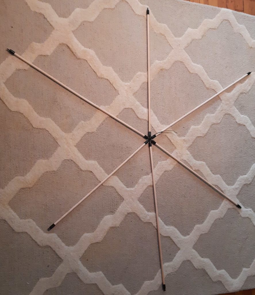
So start (step 1) by lacing a cable tie through the holes in the end caps at one end of dowels of the following lengths in order: green, blue, green, blue, green, blue. That creates vertex “A.” Feed the cable tie through its own end to secure it, and pull it some of the way through but do not pull it all the way tight yet — we will tighten up all of the vertices at the end of the construction. You should end up with something like the picture at the right. And now, it’s very important that you label the vertex you just made as vertex “A” (mark an “A” on a piece of tape and wrap it around one of the dowels at the vertex) because you will need to refer back to that vertex later in the construction.
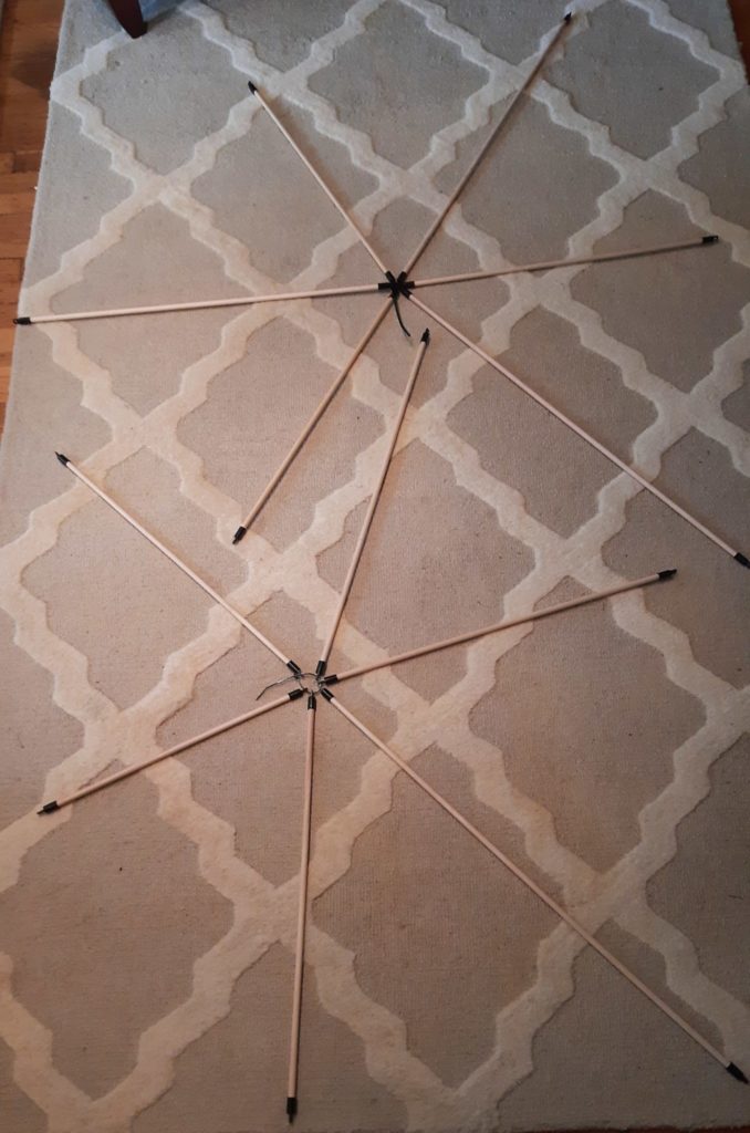
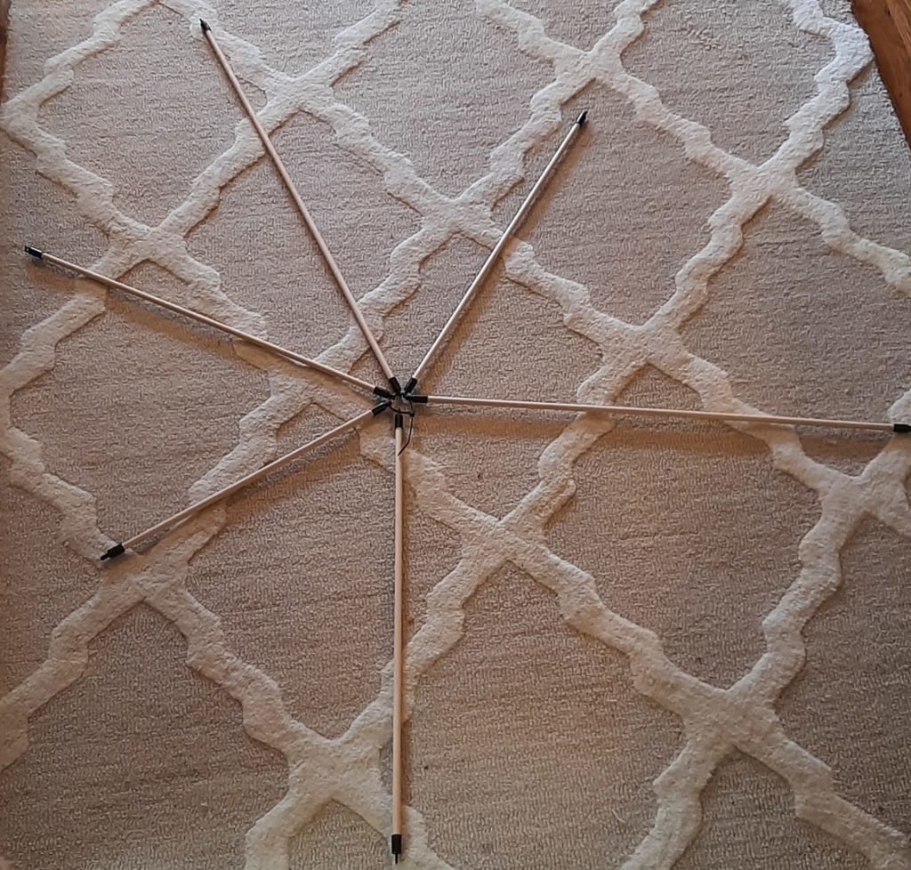
Put vertex A aside for now, and construct the following vertices (each one separately) in the same way. Remember to label each vertex as you make it! (Step 2) Vertex B’ with orange, blue, green, blue, orange, blue. (3) Vertex D’ with orange, blue, purple, blue, green, blue. And (4) vertex E’ with orange, blue, green, blue, purple, blue. At left are pictures of these three vertices (not labeled yet, so we had to go back and figure out which was which and label them after the fact — spare yourself that chore).
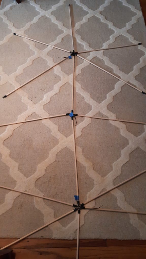
Now for (step 5) find vertex A and vertex B’ and arrange them so that the free ends of one of the blue-length dowels of A and the blue-length dowel of B’ that is between the two orange-length ones are near each other. Thread a cable tie through these free ends, including one fresh blue-length dowel between those two and one more fresh blue-length dowel after the second one. Close up the cable tie and pull it partway closed like you did with the first four vertices. Immediately label the new vertex you just created “B”. Your outcome should look similar to the picture at right (see, we finally got our labels straight!).
Now by a similar process, you should (6) join the next blue from A clockwise to the blue from vertex D’ between its orange and purple, with two new blues as before, to create vertex D. (Label it!) That gives you the following: (Vertex D is the leftmost labeled one.)
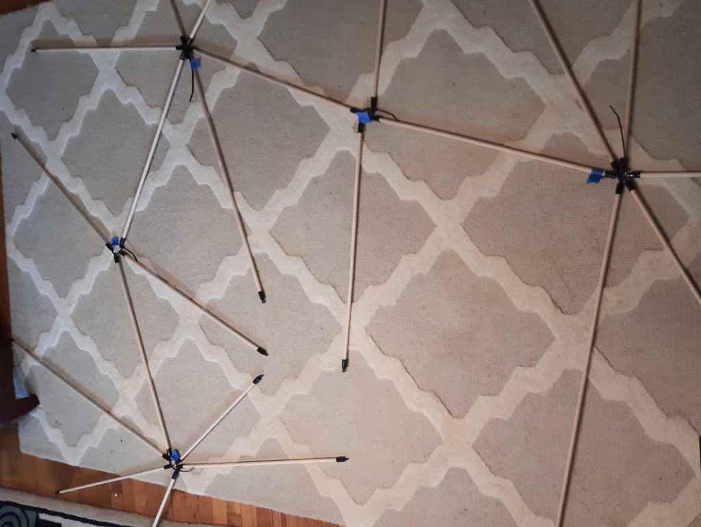
And (7) join the remaining blue from A to the blue-length dowel from vertex E’ between its orange and purple, with two new blues, to create vertex E, like so:
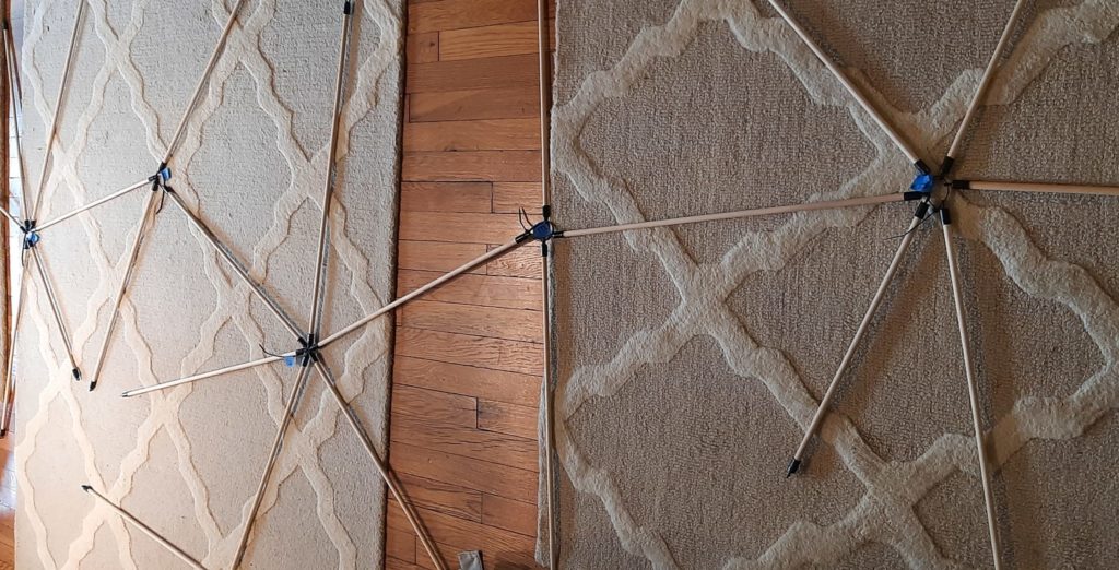
Now if you look back near vertex B that you created in step 5, you should find that the following edges all have free ends near each other in this order: a purple-length one from D’, a blue from D, a green from A, a blue from B, and an orange from B’. So (step 8) lace a cable tie through all of these in order, adding one new blue so that it will end up between the orange and the purple. Close up the tie, pull it partway through, and label that vertex C. Here’s what you get:
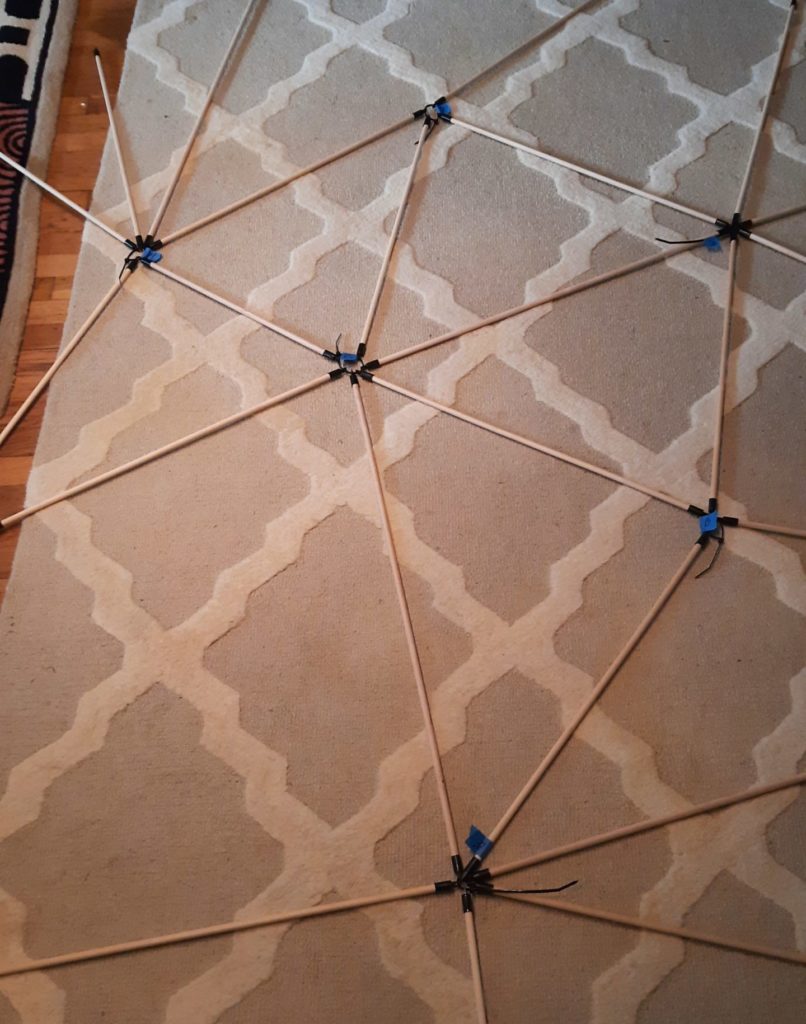
Warning: the next step is the first one in which our partial construction will no longer be able to lie flat on the floor. (Step 9) lace up the purple-length dowel from E’, blue from E, green from A, blue from B, and the other orange from B’ with one new blue-length dowel to create vertex F. You should get something like the following, where the vertex on the floor in the middle is B created in step 5 and the new vertex is at the bottom of the picture:
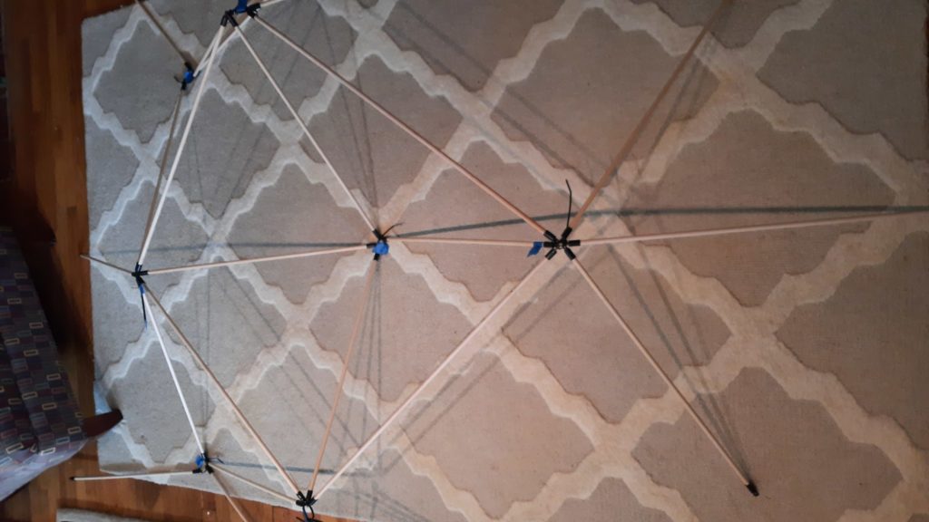
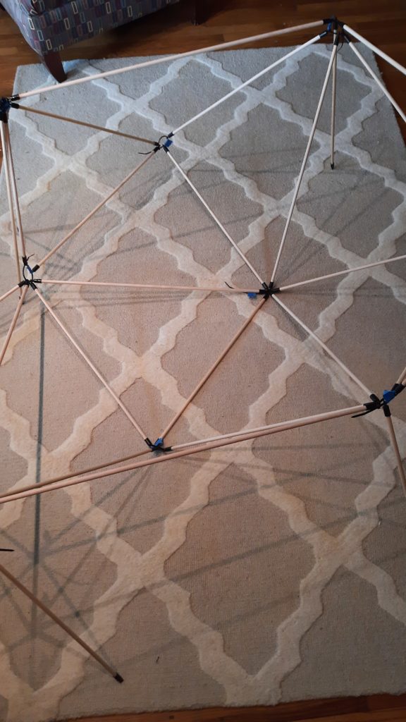
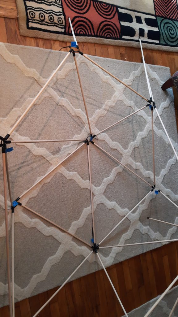
Now we have four more steps, each with just the same format as the last two. So we will list the four steps, and then follow them all by a series of four pictures showing the results after each one. (10) Connect the orange from E’, the blue from E, the last green from A, the last blue from D, and the orange from D’ with one new blue to create vertex G. (11) Connect a blue from B, the last blue from C, and a blue from D’ with one new blue to create vertex C’. (12) Connect a blue from E’, the last blue from F, and the last blue from B’ with one new blue to create vertex F’. (13) Connect the last blues from E’, G, and D’ together with the last unused blue to create vertex G’.
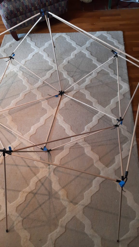
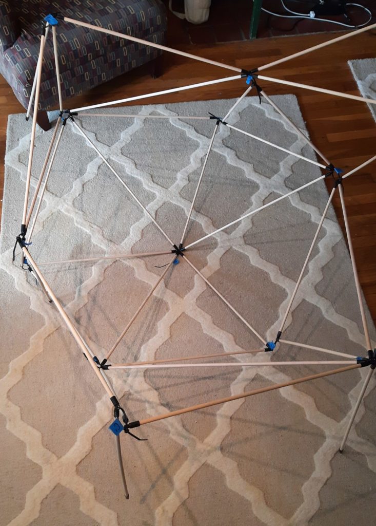
The finale:
And now, you should have exactly 6 free ends — the ones that connect at vertex H. Bring them together and run a cable tie through them. Voilà, you finally have a complete, fully three-dimensional shape. However, it won’t look as crisp as the rendering just yet:
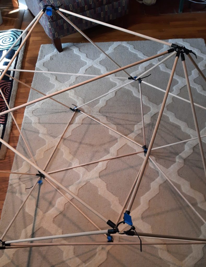
To get there, first check that your structure has the same general shape as shown. If not, back up and try to see where your connections don’t match the ones in the rendering at the top of the post and make any necessary corrections. Once it has taken on an overall shape roughly like a squashed ball, it’s time to tighten it up. Start by picking any vertex and pulling the cable tie there as tight as possible, working to get all of the tabs neatly arranged around the cable tie. Then go to the vertex farthest away from the one you just tightened, and pull that one as tight as possible, keeping the dowels linked to it as neatly arranged as possible as you do. Continue in this same fashion, always switching to the farthest-away vertex that you haven’t yet tightened up, until you have firmly secured every vertex.
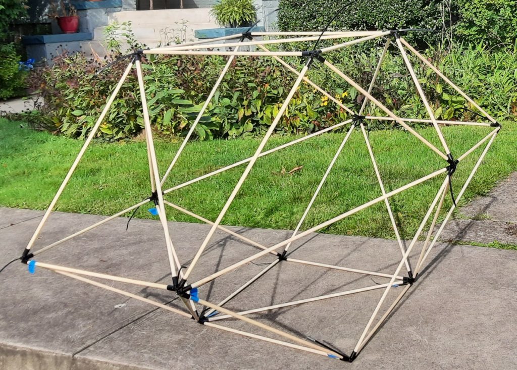
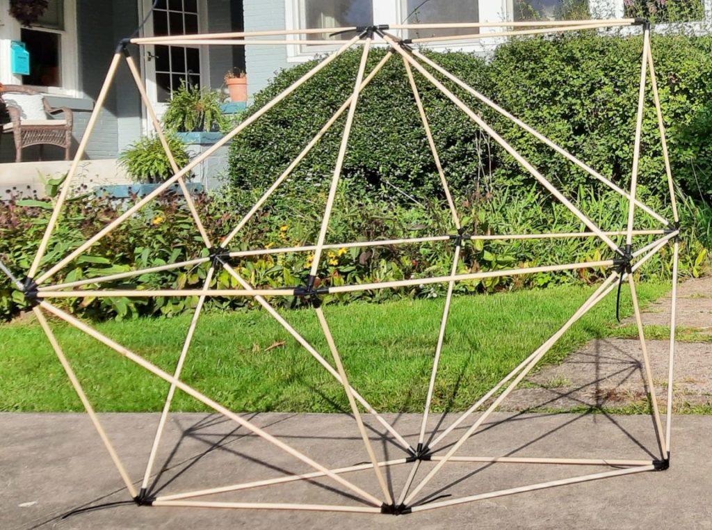
At this point, the structure should have taken on a nice, crisp polyhedral form. You should easily be able to identify the 12 planar rhombic faces, each one split into two congruent isosceles triangles by a diagonal. Here it is in essentially the same orientation as in the initial rendering, but in real life:
And as a bonus, to get a better sense of the shape, here it is resting on one of its narrow rhombus faces (and with the vertex labels removed):
Happy zipping!

