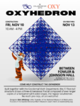
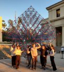
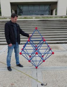
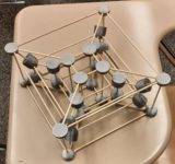
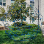
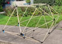
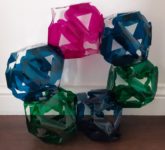
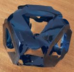
08 Apr

Modular Origami, without the origami

In many ways, modular origami is ideally suited for the type of exploratory mathematical play that S∞ is dedicated to: it’s easy to get started, very tactile, and offers nearly endless opportunities for creating interesting and beautiful objects. For example, here’s a PHiZZ unit torus that resulted from a workshop I led at The Brearley School (photo courtesy of Maggie Maluf).

But the backstory to that wonderful construction is that folding the hundreds of units required to assemble the torus took so much time that by the end of the scheduled workshop, only about a quarter of the torus was connected, and piles of PHiZZ units were strewn around the room. (Unfortunately – but unsurprisingly – I don’t seem to have a picture of this scene.) The torus was only salvaged through the valiant efforts of the school’s math club and its coach over many lunchtimes.

This anecdote highlights one weakness of modular origami – if you’re interested in building something big, folding all of the individual units necessary can be tedious and time-consuming. Hence, I’ve often wondered why there isn’t a construction toy that consists of reusable bendable pieces modeled after one of the popular modular origami units.

Two developments moved that concept from contemplation to a recent Studio Infinity project: the first is the constant improvement in hobbyist-level automated cutting machines, some of which now have dual tool slots, potentially ideal for cutting and scoring. (I use a Silhouette Cameo 4 Pro, partly because its two-foot width accommodates some materials available in bulk rolls, but there are numerous capable machines on the market – this shouldn’t be construed as an endorsement of that particular machine.)

The second was the need and opportunity for a group mathematical event for the summer 2021 Illustrating Math program at the Park City Math Institute. Since the event was virtual, it had to be easy to send any necessary supplies to the participants. Pre-cut and scored flat components seemed ideal.

I decided to stick with something modeled on the familiar PHiZZ unit for this first foray into modular origami-less construction. It also has a very simple geometry – here’s an example of a single unit:

A square sheet of paper is accordion-folded in quarters, and the resulting strip is pleated in isosceles right triangles. They usually connect in threes, as in this photo:

The idea was to create a cut/score template that would produce a piece with the same essential geometry, that could be produced in bulk on an automated cutting machine from a roll of material. In fact, choosing the material posed the first challenge. After much experimentation, I settled on the stiffest theatrical lighting gel I could find, namely Roscolene. This comes in two-foot wide rolls in a selection of striking translucent colors, and holds a crease very well, while cutting readily. Brittleness is its major drawback — I’d rather use tear-resistant mylar, but have so far had difficulty locating rolls of colored mylar sheet.

The next challenge was to figure out the connections. The paper PHiZZ units work because the initial accordion fold creates pockets that one end of the adjacent unit slides into. Since these units were to be cut from a single layer in the final 4:1 aspect ratio, no pockets were possible. (One could cut and pre-score 2:1 rectangles that fold in half to preserve the pocket mechanism, at the expense of using twice as much plastic and losing some of the translucency in doubling the layers.) Instead, venerable tab-and-slit designs can replace the pockets as a connection mechanism. Multiple prototypes led to the following design used to produce thousands of units sent to program participants:

The pink line is a score for a mountain fold, the green lines are scores for valley folds, and the red and black lines are cuts. (Of course, you can reverse mountain and valley as long as you do all of the pieces the same way, in which case your units will come out mirror-imaged from the ones below, although matching the paper ones above.) The small “divots” in the rectangle’s perimeter help align the folds along the scores. The above image is an SVG that can be used directly for cutting with the software for many machines, but if it’s helpful, here’s a PDF of the design (you can print on paper and cut by hand — but that’s even more tedious than origami), and the DXF file used to draft it.

When you have a piece all cut out and all the tabs and slits separated and folded as above, it looks like so:

To connect two units, start as shown in the left picture below: insert the large tab from the end of one unit (the orange one here) from above into the corresponding slit about a third of the way along another unit below (the blue one in the picture).

Then reach underneath the top unit and feed the thin tab of the bottom unit up through the lower slit in the top unit, as shown in the right-hand picture above. Then bend it around and back down through the top slit as shown in the picture on the left below:

Then push this tab all the way in — it’s like a belt buckle — to finish off the connection. It should look like the picture on the right above.

To wrap up this post, here’s three units assembled like the paper triad above.

The next post will cover building full polyhedra from these units.

23 Mar

Summer 2021 PCMI Illustrating Math

This post was for announcing a week-long summer workshop on Illustrating Mathematics at the Park City Mathematics Institute, this past 2021 July 19-23. It was an exciting week with lots of interesting programming including several different hands-on, how-to tutorials, keynotes by Vernelle Noel, Ingrid Daubechies, and Daniel Piker, and mathematical “show-and-ask” sessions in which a wide array of mathematicians displayed some of the intriguing and beautiful images and objects they’ve created, as well as highlighting the questions these projects have raised. (I led one minicourse on using CAD/CAM software like LibreCAD or FreeCAD in creating physical mathematical models.)

23 Mar

Woven GSD

MaterialsTools
30 equal-length rodsMeasuring Tape
32 rubber bandsScissors

This is a sequel to a (pre-pandemic) post about weaving a stellated polyhedron. This time, I’d like to show how similar techniques can also be used to create a “great stellated dodecahedron” (“GSD” for short; illustration to the left). The materials are in fact the same as before, as summarized in the table above. This time, I am using 4-foot quarter-inch pine dowels for the rods, and white mini “rainbow loom” rubber bands.

Begin by marking the same points on each rod as described in the previous post; in this case, with 48″ rods and allowing 1 inch of overlap at the ends, this is 1+(46 × 2/(3+√5)) or about 18 1/2″. (See this MathStream post for an explanation of where 2/(3+√5) comes from.)

With rods this long, it’s easiest to transfer the marks from one rod to the next.

Once all of the rods are marked, make two five-pointed stars as described for the SSD, except both of these should have the reversed over-under pattern: As you follow a given stick around the inner pentagon clockwise, it must be on top at its first junction and on the bottom at its second junction. That means also that looking at any point with the center of the star away from you, the rod that comes into the point from the right should be on top. When both stars are done, put one on top of the other so that the points alternate:

(Here the star with the point directed straight up in the picture is on top.) Now take five of the rods, stand them on end, and put a rubber band around them at the higher mark. Splay them out so that the top sections make a clockwise “whorl” when viewed from above:

Stand this “penta-pod” up amidst the two stars, with each leg just to the right of a corner of the inner pentagon of the top star:

Then slip the bottom of each leg into the rubber band at the junction it’s nearest, keeping it in the same relative position to the two horizontal rods crossing at that junction:

Now slide the top star up into the air, with each leg of the penta-pod sliding through the rubber band it was just inserted into. The legs will splay out as you do this. Keep sliding until the top star has reached the lower mark on each leg and these rods have spread out to reach the points of the lower star:

Finish this step off by inserting each leg into the rubber band at the point of the star where it’s ended up. You slide it in on the left, so that the three rods that meet at the point make a counterclockwise whorl. (As they will at every outer point of the GSD in the whole construction.) At right is a picture focused on one of the points, which will hopefully make the attachment clear.

To prepare for the next step, make another “clockwise whorl” of five rods banded together at their top marks, just like the one you made before. When that’s ready, turn the construction over and rest it on what were the top ends of the five rods from the first whorl. The construction may sag a bit, but it should hold up and balance on the five ends of the rods. The two stars should still be quite close to horizontal, with the formerly lower one (that has three rods at each point) now above the other. Overall, the construction should look something like this:

Now insert each leg of the second whorl just to the right of one of the inner junctions of what’s now the top star, as shown at left. Below right is a view of all five ends inserted.

Slide all five of these legs through the rubber bands you just inserted them into, until they reach a point of the lower star. Once there, insert the leg into the rubber band at the point of the star in exactly the same way as you did with the first “pentapod” legs. See the detail picture below left:

At this point the structure should be symmetric from top to bottom. There are five unattached rod ends sticking upwards in a pentagon, and the structure is resting on five unattached rod ends at the bottom. The ends of these rods, together with the ten points of the first two stars, comprise the 20 outer vertices of the final GSD. The star points already have all of the rods attached that they will have at completion. There are ten unused rods remaining. Each one of these will extend in a straight line from one of the top five points, through two inner junctions (one from the top star and one from the lower star), and end at one of the lower five point. From each top point, there will be one rod extending down and to the right and one extending down and to the left; and arriving at each bottom point will be one rod from the right and one rod from the left. All that remains is to feed the rods through properly so that they are woven uniformly at each junction. They should create clockwise whorls at each inner junction (when viewed from outside the GSD), and as mentioned earlier, counterclockwise whorls of three rods at each outer point of the GSD.

Here are some guidelines and pictures that should help to feed these rods through properly. We’ll begin with a rod (indicated by the green arrow in the following picture) that will extend down and to the right from one of the top points (at the extreme top left in the picture). It should feed through the inner junction of the top star that is immediately below and to the right of the top point; that’s the one with the white rubber band in the lower foreground of the picture. Specifically, it will feed through the leftmost sector of this junction:

It then feeds through the inner junction of the lower star just below and to the right of that, but this time it feeds through the rightmost sector of that junction. The new rod then proceeds down to the end of the lower leg that’s just below and to the right of that. The next picture shows just the one new rod added, in its final position. The new rod is again indicated by green arrows; pay particular attention to how it passes through the two inner junctions: all the way on the left at top, and all the way on the right for the lower one.

The next rod we’ll feed through will run from the upper point next counterclockwise (as viewed from the top) from the one we just attached to, and proceed to the left through the same inner junction that we just used. This will add the fifth and final rod to that particular inner junction of the upper star. As with the previous rod, we’ll insert it in the leftmost sector of that junction. Here’s the rod (we’ll continue indicating the newly-added rod with green arrows for the rest of the post) just after it’s been properly threaded through the rubber band at that inner junction of the top star:

Keep feeding it through until it reaches the inner junction of the lower star just to the left; there, as before, feed it through the rightmost sector of the junction:

Once it’s through that rubber band, continue feeding it until it reaches the end of the bottom leg below and to the left of that junction:

Make sure you secure it at the top as well. Now you’re in the home stretch — just eight more rods to insert. It’s most straightforward to insert them in pairs, just like the previous two, rotating the structure one-fifth of a turn before each pair to orient the location for their insertion toward you. Here’s the structure after just one more rod has been inserted:

For every rod that you insert, it feeds through the leftmost sector of the junction where it passes through the top horizontal star, and the rightmost sector of the junction where it passes through the bottom horizontal star. You can see this again in the following picture of the fourth rod in the midst of being inserted: (125302 goes here)

You should also see a regular icosahedron begin to emerge at the core of the GSD. Here’s a view just before the sixth rod is secured to its top point:

If you just keep going in this same fashion for all ten of the last group of rods, you’ll complete the star. Here’s a view just after the last rod is inserted:

And now you’re pretty much done! There’s really only a couple more optional steps you might want to do to get your great stellated dodecahedron into optimal shape. As depicted at right, you can examine and gently adjust each of the inner junctions of five rods (that form the vertices of the inner icosahedron) to ensure that each one makes a tidy regular pentagon at the five-way crossover. In addition, if you’ve built your GSD from rods with even a moderate amount of surface friction (dowels, paper straws, even metal rods), you can now snip the rubber bands off of all of the interior, five-way junctions and the GSD will hold together just fine. (Theoretically, you can cut the outer rubber bands at the points where three dowels come together as well. If you want to try this, I recommend just trying a couple of widely-separated ones at first, and leaving off if the outer junctions don’t seem to be holding up well. I pretty much reserve this for stars built out of really highly frictional items or ones that can be twisted a bit at the outer points, like pipe cleaners.)

It’s a bit of an involved building process, but I think the elegance and symmetry of the final construction are well worth the effort. Here’s a picture of the final result with inner rubber bands removed:

In addition, you’ll find that the finished GSD is surprisingly sturdy and robust. You can easily pick it up and handle it without fear of it falling apart. As an illustration, here’s a closing shot of the great stellated dodecahedron supported on just one point:

19 Mar

Wiredodeca

After seeing Laura Taalman’s inspiring 3d print, it occurred to me that one could also render the edge-to-edge cubical array of dodecahedra contemplated in this earlier post in an analogous way. Plus, I just received a new Prusa SL1 printer, and needed something to try it out on. So after just a bit more tinkering in OpenSCAD, and 400 minutes of print time using the resulting STL file, I ended up with this model:

If you recall, the negative space of the dodecahedron array was just a bit too monotonous to seem worth printing. However, I think that simplicity works very much to advantage in this wire-frame style of rendering. This model has enough complexity to afford visual richness, but is open and orderly enough not to be overwhelming.

In addition, it produces an excellent variety of shadows (or parallel projections, in more math-y lingo):

(The rhombuses in the top left photo correspond to the rhombic prism channels in the antidodec that we previously modeled.) Here’s another shot so you can see the setup for capturing the shadows. This is really best done in direct, bright sunlight — it’s tough to get such crisp, parallel rays of light otherwise.

I can’t resist one more take on this lovely model and its shadows.

If you print one of these or a variation on it, I’d love to see/hear about it.

12 Mar

Wirecosahedra

When I showed this recent post to my friend and colleague Laura Taalman, aka mathgrrl, she suggested that another approach to creating a model of the underlying structure would be to construct the icosahedra themselves (rather than the negative space), except use wireframes of the icosahedra rather than solid ones to avoid obscuring all of the internal structure. Her encouragement motivated me to create a new OpenSCAD file for this. Taking pity on the small size of the build plate of the 3D printer that I have access to, Laura even printed the resulting STL file for me. Her machine produced the following lovely results:

Whichever one you like better, this or the Anticos, I think it’s safe to say that the two models bring out different aspects of the same edge-to-edge arrangement of icosahedra. For example, this “wirecosahedra” structure shows better how the edges of neighboring icosahedra coincide. On the other hand, I think if we had only produced this model, it would be hard to discover the octahedra lurking in the corners between the icosahedra — they get a bit lost among all of the edges.

Thanks to Laura for providing another perspective on this arrangement of Platonic solids!

09 Mar

Anticos

Judging from at least one of the previous projects, Studio Infinity is intrigued with connecting polyhedra edge-to-edge. (Of course, connecting them face-to-face is interesting, too, but that’s pretty familiar from Legos and such; and vertex-to-vertex is the same as connecting dual polyhedra face-to-face.)

As you can see in the “blueprint” for the Boxtahedral Tower at right, connecting solids in this way often highlights symmetries that might otherwise be overlooked. In that case, edge-to-edge connections illuminated the threefold symmetries of cubes.

Even more surprising is that the most spherical of the Platonic solids, the icosahedron, can nestle into a cube with six of its edges just brushing the faces of the cube:

That means that if we connect icosahedra edge-to-edge, we should be able to make rectilinear structures, like with ordinary building blocks:

I wanted to find a way to show what was going on in this structure; but it seems as though the individual icosahedra get in the way of seeing the overall picture. You can’t see many of the actual edge connections at once.

Sometimes, however, what’s not there is even more illuminating than what is. Thus, the “Anticos” emerged: the negative space of the above configuration.

(More precisely, I enlarge each icosahedron by about 35% before carving it out of its respective cube. That step creates the “windows” in the sides of the cubes that lets you see the internal structure — without the enlargement, there would just be an infinitesimally narrow slit in each surface, so you would see nothing but a stack of cubes.)

Although usually S∞ focuses on structures that you can build by hand with ordinary materials, for something this intricate and detailed 3D printing seemed to be the only reasonable route to get a physical example in a reasonable amount of time. So here is the OpenSCAD source file and the resulting STL file. Since all of Studio Infinity’s content is Creative Commons-licensed, feel free to modify however you may like, and print if you have access to a 3D printer.

Now the icosahedra are revealed to embed in a lacy network of octahedra connected by rhombic prisms:

Although after the fact it may not be a mathematical surprise that octahedra show up between the icosahedra, it’s still visually striking, and I’d say that creating the physical model heightens our appreciation of how they all fit together. Moreover, physical models can reveal other surprising aspects of the underlying geometry. For example, this half-height prototype of the Anticos reveals a lovely network of hexagonal cross-sections of the packed icosahedra:

Hopefully, S∞ will have much more to say about connecting polyhedra both face-to-face and edge-to-edge in the weeks to come.

08 Mar

Antidodec?

This MathStream post about why an icosahedron inscribes in a cube also shows that a dodecahedron fits into a cube in an analogous way. That raised the prospect that it might also be worth building an “Antidodec” analogous to the Anticos. So I quickly mocked one up in OpenSCAD (here’s the two files you need), producing the following image of what it would look like:

Surprise! it’s just a rectilinear network of (infinite golden) rhombic prisms. While it’s striking and lovely in its own way that this structure turns out to be so simple, it didn’t seem that the result would be visually interesting enough to be worth producing physically. So in the end, this post is really just a footnote to the prior project.

07 Dec

Math’s Bubbling (not) Over

Here’s a large-scale model I designed of the Weaire-Phelan space packing, built by the participants of the Fall 2019 semester on Illustrating Mathematics at ICERM in Providence. The title above is a reference to the fact that it is still not established whether this is the most surface-area parsimonious way to divide space into cells of equal volume, like an ideal foam in which each bubble encloses the same volume.

17 Sep

Woven SSD

It’s high time that S∞ got back to its core: mathematical constructions you can build. Here’s an attractive star-shaped polyhedron made with a weaving technique that I am indebted to Jürgen Richter-Gebert for introducing me to. It’s called the “small stellated dodecahedron,” and is one of the MaterialsTools30 equal-length rodsScissors32 rubber bands

To build this, you first need 30 rods all the same length, made of some material that has a bit of give (hint: not glass rods). You can choose almost any material; here, I’ve used mostly aluminum tubes, with five contrasting brass tubes of the same diameter to highlight the first star you make. Possibilities include thin dowels, bamboo strips, pipe cleaners, and more.

You also need 32 rubber bands. They should be sized so that it’s easy enough to get them around five rods simultaneously, but then they should hold that thickness of material securely (of course you can double or triple up the bands if need be). You can use almost any type of elastic bands: ordinary office rubber bands, colored hair elastics, or rubber O-rings as I’ve used here.

Before you get started assembling the SSD, you should mark the locations that the rubber bands will go on each rod. To find these locations, first pick an amount of each rod that will extend past each vertex for security of the connections. For example, I used 18-inch rods, so I chose that the rods would extend 1/2 inch past each vertex. If you are making a larger version, you’d want to pick something longer; if you are making a smaller SSD, I wouldn’t go much below 1/2 inch because the vertex connections might start slipping apart too easily.

Subtract twice the amount you are leaving at the vertices from the length of the rods to get the distance between the vertices. In my case, that’s 18 – 2×(1/2) = 17 inches. Now multiply this value by 2/(3+√5); for 17 inches, this gives about 6.49 inches. (See the MathStream post that explains this calculation.) Finally add back in the amount you’re leaving at the vertices; this step gives me 6.99 inches, which we should of course round to 7 inches. That’s the distance you want to mark on the rods from each end (two marks per rod). With my 18-inch rods, I just lay them next to a ruler and mark at 7 and 11 inches.

Ok, now all is ready for construction. The basic step you’ll be doing over and over is placing two rods side-by-side and putting a rubber band around both of them and sliding it down to the first mark on the rods.

We’ll call this basic unit a “linked pair.” Take two linked pairs and put them side by side with their connections on the same side, and put a third rubber band around one rod from each pair at the ends opposite the existing connections. Slide the rubber band down so that you have a zig-zag chain of four rods.

Connect a fifth rod to one at either side, continuing the zig-zag.

Now connect the free end of this fifth rod to the free end of the first rod of the zig-zag, as shown on the right.

This is a configuration that you can now wiggle around until it forms a five-pointed star, as shown to the left. Important: looking at the two junctions on each rod, the rod must be underneath at the first junction and on top at the second junction as you proceed clockwise around the inner pentagon. Make sure that every one of the five rods follows this pattern before continuing, It’s this under-over, under-over pattern that constitutes the weaving in this construction, and that same under-over, under-over will continue throughout the entire construction.

Next, at each of the points of the star you’re forming, you can slip one rod under the other to continue the under-over junction pattern of the rods. These points of the star will eventually be vertices of the SSD.

Add a rubber band to secure each of the points, and congratulations, you’ve just made your first star out of 12.

To continue toward the SSD, take five rods and line them all up and put a rubber band around all five of them and slide it down just a short way, roughly the amount you decided to leave at the vertices above. You should then be able to splay the rods out so that the far ends are at the points of a pentagon, and there is a little clockwise swirl of the near ends of the rods (see the picture to the right).

Place each of the far ends just counterclockwise of one of the internal junctions of the star you made, in order around the star (as shown on the left).

Insert each of the far ends into the rubber band at the corresponding junction, making sure to keep it within the triangle of the star that it started in.

Now push all of the five new rods through those junctions until the second mark reaches the junction. That completes the first full vertex of your SSD.

If you look at your structure in progress from the side, you will see three out of five sides of another star. We want to complete that to a full star. So take a linked pair, and link one free end of the pair to each of the two sides of the star sticking out. Push those links in a little way and make sure the junctions all continue the under-over pattern of the first star. If all looks well, you can slide all of the connections until they reach the marks.

To complete the second star, slip the points of the star past each other as you did with the first star, and secure with rubber bands (there will already be rubber bands for this in place at two of the vertices).

Now rotate the structure 1/5 of a turn around the original star. You’ll see another star with only three sides in place. You want to complete this in a similar fashion. The only difference is that this time, you only make one entirely new link; at the other end of the linked pair you’re adding, you feed the rod through the existing rubber band at an internal junction. Make sure to continue the same under-over pattern throughout. The new rod should pass through a triangle in the second star that does not yet have a rod passing through it (it should not pass outside the second star or through the pentagon of the second star).

When that one’s done, add two more linked pairs to complete two more stars in exactly the same fashion.

The next linked pair is very similar to these; you just have to feed both of its free ends through existing junctions. When that’s done, you’ve finished six of the twelve stars in the SSD.

To continue from here, take a single rod (not a linked pair) and feed it through any of the partial vertices and the nearest internal junction that only has two rods at it, as shown.

Adding that rod will create a new partial star with three edges in place. Complete that one just the way you did the third star.

You’re getting close now. Complete two more stars like the third, and then one like the sixth.

That leaves just a single line of four junctions that does not have a rod going through them (shown down the middle of the image above). Carefully insert the final rod through all four junctions – it’s probably easiest to pass it through the two internal ones first, then tuck the two ends in at the vertices, to produce something like this. (This last edge is again down the middle of the image below.)

Now comes the exciting final part: cut away all of the rubber bands at the internal junctions. They were just there to stabilize things during construction; they’re not actually needed to hold the SSD together once it’s built, thanks to all of that weaving that we did. And voila!

In fact, if you used a high-friction material like bamboo strips or pipe cleaners, it’s often possible to cut away the rubber bands at the vertices as well. I don’t have a picture of this, as the metal rods are too slippery for the vertices to hold. If you want to try, just proceed carefully, and if any of the vertex junctions “pop,” tie it back up immediately and don’t cut any more (unless you want to quickly revert to a pile of separate rods).

If you like this construction and happen to be in Providence on 2019 Sep 28, come to the ICERM Open House at WaterFire Providence and help build a glowing version with 10-foot pipes for the rods!

30 Jul

Problematic Postcards

If you’ve come here as a result of a puzzling postcard you may have come across, welcome to Studio Infinity! We hope you’ll enjoy looking at some of the other content below as well, but here are the three posts corresponding to the problems you can find on those postcards, each of which links to a solution.

Insubordinate Integral
Smallish Sequence
Troubling Triangle

And, as I’ve mentioned here before, I invite you all to submit a problem or solution to Math Horizons Playground.

29 Jul

More Life at a glance

A few days after the event at TCNJ, students at the PROMYS program at Boston University built another “Life sculpture” in which each layer is a generation and time proceeds downwards. Here, we explored questions of how you might know things like whether the resulting “sculpture” would be connected, or whether it would be self-supporting. For these types of questions, what one really needs is to solve the (more computationally thorny) “inverse Life” question: what colonies of cells can give rise to a given configuration in the next generation?

This sculpture begins with a pattern in its top layer that will eventually result in four Life “gliders” proceeding in different directions, which would then serve as four “legs” for the sculpture to stand on. Unfortunately, we didn’t quite have time to build enough generations to see the four gliders diverge.