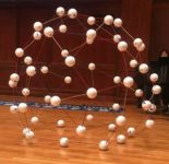

Perfect Alignment in Reflections
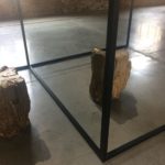
These images were taken during the summer of 2017 when I attended the Biennale in Venice on an exhibition in the main pavilion section, “Viva Arte Viva,” of the Biennale. This exhibit – WeltenLinie (One in a Time) – by Alicja Kwade uses powder-coated steel, mirror, stone, bronze, aluminum, wood, and petrified wood. The objects are placed on either side of mirrors so that as the viewer walks past, the actual object is replaced by the reflection of another, perfectly lining up as the viewer moves past to create the illusion of a whole object, except with different materials making up each the reflected and actual objects.
Read More