
More Life at a glance
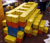
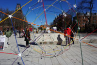
A few days after the event at TCNJ, students at the PROMYS program at Boston University built another “Life sculpture” in which each layer is a generation and time proceeds downwards. Here, we explored questions of how you might know things like whether the resulting “sculpture” would be connected, or whether it would be self-supporting. For these types of questions, what one really needs is to solve the (more computationally thorny) “inverse Life” question: what colonies of cells can give rise to a given configuration in the next generation?
Read More