25 Oct

Announcing the Oxyhedron

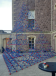
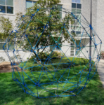
Studio Infinity has teamed up with Prof. Jim Brown and the Occidental Math Dept. to create the Oxyhedron on Friday, 2023 Nov 10, starting at 10 AM. The installation will take place just outside Fowler Hall, which houses the Math Dept. I did a site visit today; on the right you can see the quarter-scale mockup being used as a stand-in to plan the event, held in place by Jim.

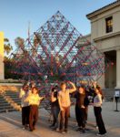
The structure we’ll be building is the octahedron analogue of the Sierpinski tetrahedron that formed the basis of Fort Sierpinski on the campus of Lafayette College last fall. It will consist of 1,968 rods and 457 hubs from The Ultimate Fort Builder construction set distributed by Lakeshore Learning.

Below is the poster announcing the build (note the image is to scale). Anyone reading this who will be in the area on Nov 10 is welcome to attend. More details and pictures will be posted as the event unfolds.

28 Oct

Fort Sierpinski

I’ve been the primary architect of a number of constructions of

So when I discovered that the Lakeshore Learning Ultimate Fort Builder construction toy allowed rods to be connected at all of the angles necessary to construct arbitrary portions of an octahedral-tetrahedral lattice, I knew that I had no choice but to eventually seek yet again to scale this tower of three-dimensional fractality.

The opportunity came in the fall of 2022, when my colleague Prof. Alissa Crans put me in touch with Profs. Derek Smith and Ethan Berkove, who were interested in holding a collaborative mathematical construction outside the math department’s building on the Lafayette College campus. After reviewing a number of proposals, they (to my delight) selected a Sierpinski tetrahedron constructed from the Fort Builder toy. They felt this structure would tie in to a number of classes being held that semester, including one on combinatorics — just how many rods and joints are there in that pyramid, anyway?

This post will be fleshed out as time permits, but for now suffice it to say that the construction — quickly dubbed Fort Sierpinski — came together very satisfyingly (more below).

The final structure came in at just a few inches shy of twenty feet tall, making it the largest Sierpinski tetrahedron I’ve been involved in yet, as well as the highest-order approximation: there are five generations of tetrahedra, from the smallest unit tetrahedra to the construction as a whole.

If you look closely, you will find just a few connections where the ability of the hub-rod sockets to take tension trying to pull them apart had to be augmented with a little strategically-placed tape (as hinted by the items on the table in the foreground). Other than this kind of patching (after all, kids do have to be able to take their creations apart by pulling out the rods, and this giant building is putting a lot of tension on certain junctions), the Fort Builder toy turned out to be quite up to this gargantuan task.

11 Oct

Rhombiglobe

For this construction commissioned by the Dickinson College mathematics department, we chose a construction technique that goes all the way back to a construction from 2016, but this time with a twist. All previous installations done with this technique used only one length of rod, producing rigid equilateral polyhedra. But I had long wanted to construct a rhombic enneacontahedron, a shape that George Hart introduced me to with one of his artworks. Although that polyhedron is equilateral, consisting of 90 rhombi of two types, it is not rigid by Cauchy’s Theorem on polyhedra: each face is a quadrilateral, and so no face is by itself rigid. Hence, it’s necessary to brace the rhombic faces. Since there are two different face shapes, that means there are two additional rod lengths for the lengths of diagonals of those two different rhombi.

Further, the sponsors decided to proceed with a design in which the rods were colored to correspond to the ice caps, land masses, and oceans of our planet Earth, in honor of the world in which we live and a contemporaneous conference on climate change and other ecological issues.

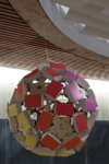
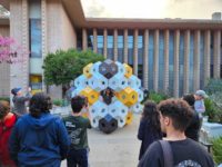
This post will be fleshed out as time permits, but here’s a picture of the completed construction on site at Dickinson college (more below):

This photo is taken from a viewpoint over the southern tip of Mexico and the Central American land bridge to South America (since there are “only” 180 edges to this polyhedron, the representation of land masses is by necessity quite approximate). For comparison, here’s an image of the pre-build rendering of the Rhombiglobe from essentially the same viewpoint:

You may notice the actual construction has a decidedly “non-spherical” aspect on its left, in the midst of the Pacific Ocean. That phenomenon was perplexing in the midst of the build, but later analysis revealed that it was a direct side effect of there being nine different types of pieces: three colors of rod in three lengths each. One of the participants in the group construction inadvertently swapped one of the longer and one of the middle-sized blue rods in the neighborhood of the bulge. The result was that by dint of perseverance, we managed to construct a geometrically “impossible” polyhedron, which naturally adopted a non-spherical shape as it attempted to resolve all the extra stress that the incompatible edge lengths created.

23 Apr

Pythagoras Cubed

I was recently invited at the last minute to lead a mathematical construction for a seminar for math majors at Loyola Marymount University. The hope was to create something physical connected with one of the topics in the course, which linked the history of mathematics with various unsolved problems, among other things. Since there had been a fair amount of discussion about the Pythagorean Theorem, we settled on the following construction that demonstrates an interesting and less-familiar related phenomenon in three dimensions.

Given any three lengths, you can build a tetrahedron with a vertex where three right angles meet, and the lengths of the three edges meeting there are as given. (Basically, just cut off the positive coordinate axes to the three given lengths and join the resulting endpoints with a triangle.) Such a tetrahedron is called a “right tetrahedron” and those three initial lengths are called the “legs.” The following construction (erecting a prism on each face whose height is the same as the area of the face) can be performed with any lengths for the legs, but all of the calculations below are done for legs √6, √19, and √30 (which have the pleasant property that the sides of the fourth tetrahedron face are then 5, 6, and 7, as shown in the diagram to the right). To create a human-sized result, I used a decimeter as the length unit; if you wanted to make this into a tabletop-sized construction, you could scale it down by a factor of four or five — but note that when scaling down the edge rod lengths (as opposed to the altitude lengths) you need to add one centimeter, divide by your scale factor, and subtract off the one centimeter again, to allow for the extra length created by the connectors.

MaterialsTools
About 30 1/8″ diameter rods, at least 147 cm long (5′ suffices), for example wooden dowels or fiberglass rodsMeasuring tape
About 90 custom connector clips (STL file, or OpenSCAD file if you need to tweak them)Meter sticks
Three sheets of foam core, at least 70 cm by 50 cm (30″ by 20″ suffices)Cutting pliers or small saw (for cutting rods)
Plastic wrap (ideally four colors of industrial-size rolls)Box cutter (for foam core)
At least 225 liters of loose fill material (e.g. packing peanuts); 9 cu. ft. sufficesScissors
If rods expand after cuts:
Optional: thick paper or cardstock for temporary lidsGripping pliers
Drill slightly larger than 1/8″ (e.g. 9/64″)

Assemble all of the needed materials and tools, and fabricate the connectors per the supplied STL file. [vrm360 model_url=”http://studioinfinity.org/wp-content/uploads/2022/04/DowelSnapV6.stl”]

A row of freshly printed connectors before
removing the support material
One finished connector ready for use
Length (cm)QuantityFor
1473altitude D
119.43altitude C
699edges of C and D
67.13altitude B
598edges of B and D
53.87edges of B and C
53.43altitude A
498edges of A and D
42.66edges of A and C
23.56edges of A and B

Then begin by cutting lengths of your edge rods as in the table to the right:

Because the vendor-supplied cut ends of the edge material will likely be more uniform than your hand-made cuts, especially if you choose to use cutting pliers, try to preserve as many of the manufactured ends as possible when cutting.

Next, slide connectors onto both ends of each of the rods designated for “edges” in the table above. With the fiberglass rods I was using, the ends I hand-cut with pliers deformed and expanded, so I had to ream the holes of the connectors for these ends out to 9/64 inch by hand-twisting a drill (held by gripping pliers) into the holes.

Cut a foam-core bottom for each of the prisms, corresponding to the four faces of the central tetrahedron: the largest face D has edges 50, 60, and 70 centimeters (I just measured off 70 cm along one edge of a foam-core sheet, and then laid meter sticks down so that their corners met and they read off 50 and 60 cm respectively at the corner and marked point on the edge). The other three faces A, B, and C (in order of increasing area) are all right triangles, so I just measured the leg lengths along two adjacent sides of a sheet and then cut the resulting corner piece off. The lengths are: A – 24.5 and 43.6 cm, B – 24.5 and 54.8 cm, and C – 43.6 cm and 54.8 cm. (Note the edge lengths of the foam core faces are all 1 cm greater than the corresponding edge rods, because the connectors at each end of a rod add exactly 1 cm to their effective length.)

Assemble each of the prisms by clipping edges onto altitudes to form the desired cross section.

Every prism should have a triangle of edges at each end of the altitude, and at least one additional group of edges around its middle; the quantities above have been set so that the tallest prism D can have three internal sets of cross braces and B can have two. One set of cross braces at mid-height for prisms A and B seemed to be plenty. Note that the clips can interleave at the ends to produce triangles with coplanar rods, except for the two most acute angles (the sharpest angles of triangles A and B), where you will have to place them side by side. You can actually get a bit more stability on the taller prisms by staggering the interior cross braces slightly, rather than making each set coplanar. But on all of the prisms, the cross braces at the ends should be as close to coplanar as possible.

When you have made all the prism frameworks, attach the foam core bottoms to each prism with tape. For the finale, it matters a bit which end of each prism you attach the bottom to, and this is an aspect that was unfortunately not done correctly in the pictured build. The easiest way to get it right is to stand the D prism in the center, and then line up the A, B, and C prisms with their hypotenuses matching with the sides of prism D. Orient A, B, and C so that the legs of adjacent prisms match in length (see the diagram at left). Then attach the bottoms.

The last step in preparing for the finale is to add vertical sides to your prisms. This could be done with any sheet material (you could cut rectangles to size) but the quickest and easiest way, that also allows you to easily see what’s going on in the finale, is to wrap them with cling wrap. Industrial packaging wrap is readily available in a variety of colors, or you can use ordinary consumer food wrap (although you will likely need an entire roll). Begin the wrapping at the top by hooking the wrap onto one of the altitudes (see photo at right), and then leaving some extra wrap above the top crossbars, make one circuit of the triangular perimeter. Fold the extra down around the top crossbars, and then continue to wrap around the prism angling downward somewhat so that at least half the sheet overlaps with what’s already there at all times. Continue past the bottom panel of the prism, and then fold the excess underneath and secure with tape or by stretching and sticking the wrap to itself. The process and results are depicted below:

Once all of the prisms are wrapped, it’s time for the finale. Fill the three smaller prisms A, B, and C with loose, light filler material — we used water-soluble “packing peanuts.”

Ideally, if the bottoms are placed on the proper sides, you can now place loose temporary lids on top of prisms A, B, C, and invert them above prism D to create a space congruent to the right tetrahedron above prism D, showing the prisms of height equal to face area erected on all four faces of the tetrahedron. (See diagram at left for how that might look.) Then pull the temporary lids out and allow all of the filler material to tumble down into prism D.

If that’s too complicated or the bottom panels were not on the correct ends, simply dump all of the contents of A, B, and C in turn into prism D (as depicted to right). Here’s what you get when you’re done:

And voilà — the material exactly fills the largest prism D! Is this a coincidence? Seeing as how this is Studio Infinity, of course not. What are the volumes of these prisms? Well, letting A, B, C, and D also stand for the areas of the four faces, we have the height of prism A is also A, and so on through the height of prism D is D. And since the volume of a prism is the area of its base times its height, the volumes of the prisms are A2, B2, C2, and D2. And it turns out that for any right tetrahedron, A2 + B2 + C2 = D2 — this is the Three-D Pythagorean Theorem. So the big prism was guaranteed to fill up exactly!

(Many thanks to the students of LMU Math 490!)

09 Apr

Truncated Triakis Tetrahedron

Materials
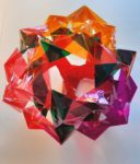
42 modular units cut out and folded (see Modular Origami, without the origami)
(preferably 9 each of four colors and 6 of another)

For the actual building event mentioned in the previous post (linked above), participants could choose from a variety of target polyhedra. The origami inspiration was the PHiZZ unit, which stands for Pentgons Hexagons in Zig Zag, so the ideal targets consist of just pentagons and hexagons. With Euler’s formula for polyhedra and a little calculation you can determine that such a shape must have exactly twelve pentagons and almost any number of hexagons; the page for the event includes a table of candidates.

I chose the Truncated Triakis Tetrahedron as my target: (not only because of the alliteration, it’s a nice size and has pleasing symmetry that breaks the building down into four simple, identical sub-assemblies)

To assemble this, I worked from a diagram of the edges, graciously colorized by Elliot Kienzle:

I found it easiest to start by making each of the lighter-colored sections. They’re all the same, made of nine pieces each. You make one three-way connection all the same color (as shown in the previous post), and then turn each of the three opposite ends of each of these pieces into a three-way connection, like so:

Repeat with the other three colors.

When you have your four sub-assemblies, you can connect two neighboring loose ends of one color with corresponding loose ends of another color at the two ends of a new unit of the darker color. Here are the components laid out schematically to show how they go together:

And here they are overlapped in the actual way the first trio of connections will be made:

And here they are once both ends of the blue unit have been fully connected:

This process of connecting sub-assemblies with one additional unit happens in six places, shown by the blue edges in Elliot’s diagram above. (These six edges are actually the remnants of the six original edges of the tetrahedron that the truncated triakis tetrahedron is based on.) Once you’ve made all those links, everything hangs together like so:

(Note that this image is shown from the same perspective as Elliott’s diagram above, used as the construction guide.)

Participants took this basic concept in a variety of directions, and here’s a mini-gallery of some of the results:

Emily Z
Katherine Booth (75 edges!)
Kate Stange
Rémi Coulon
Gabriel Dorfsman-Hopkins
As a final bonus, the units are flexible enough so that you can break the pentagon/hexagon only rule: this shape is made by connecting just two of the truncated triakis tetrahedron sub-assemblies to each other in all three possible places, and it contains three quadrilaterals and six pentagons.
07 Dec

Math’s Bubbling (not) Over

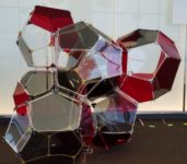
Here’s a large-scale model I designed of the Weaire-Phelan space packing, built by the participants of the Fall 2019 semester on Illustrating Mathematics at ICERM in Providence. The title above is a reference to the fact that it is still not established whether this is the most surface-area parsimonious way to divide space into cells of equal volume, like an ideal foam in which each bubble encloses the same volume.

29 Jul

More Life at a glance

A few days after the event at TCNJ, students at the PROMYS program at Boston University built another “Life sculpture” in which each layer is a generation and time proceeds downwards. Here, we explored questions of how you might know things like whether the resulting “sculpture” would be connected, or whether it would be self-supporting. For these types of questions, what one really needs is to solve the (more computationally thorny) “inverse Life” question: what colonies of cells can give rise to a given configuration in the next generation?

This sculpture begins with a pattern in its top layer that will eventually result in four Life “gliders” proceeding in different directions, which would then serve as four “legs” for the sculpture to stand on. Unfortunately, we didn’t quite have time to build enough generations to see the four gliders diverge.

27 Jul

x-y-t Life

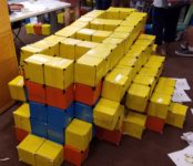
Here is a photo of the first 13 generations of the evolution of the “R” pentomino pattern in John Conway’s Game of Life. Each layer represents one generation, and time proceeds downwards. In each layer, live cells are represented by boxes. The color of the box indicates how many generations that cell has been alive: yellow for one, orange for two, and blue for three or more. These “Life sculptures” were built by middle-school students at The College of New Jersey in 2019 July.

(If these boxes look familiar, you’re right – they are the same ones from the Boxtahedral Tower reused for a completely different construction.)

17 Apr

Spectral Snub

Here’s an image from inside one of a pair of mirror-image snub dodecahedra built by passersby on the Harvard Science center plaza in 2019 April. The completed work, “Spectral Snub”, was on display inside the Science Center for the following four days. Photo courtesy of Stepan Paul.

07 Nov

Deltahedral Torus?

Here’s a torus built from equilateral-triangle Geometiles that I used as a prop for an undergraduate talk at Harvard University in the Fall semester of 2018. Actually, the structure it is based on is not mathematically exact; the triangles theoretically are isosceles triangles of sides 1, 1, and 0.998, but there is plenty of give in the real world to construct it physically. As far as I know, it remains an open wuestion whether there is a true deltahedral torus in which all vertices are hexavalent.

21 Oct

Tetrahelix

This is a placeholder post for pictures of an installation I led on 2018 Oct 21 at the Mathematical Sciences Research Institute, entitled “Tetrahelix”. It consisted of a double helix, one strand of which was composed entirely of regular tetrahedra connected face-to-face (such compounds can reach any point in space and come arbitrarily close to closing in a loop but can never make a mathematically perfect loop), and the other strand of which was the combinatorial dual of the first, realized by a geometric structure that can only be thought of as a “polyhedron” in a relaxed way. When I get a chance, I will post the construction techniques and math behind this installation.