14 Apr

Call for Puzzles

Hey, I have recently become problem editor for the undergraduate Math Horizons magazine of the Mathematical Association of America. So I’d love if you have problems/mathematical puzzles to submit to the column. The official submission blurb follows, and of course you will be credited in the Magazine.

The Playground features problems for students at the undergraduate and (challenging) high school levels. Problems or solutions (including more elegant or extended solutions to Carousel problems) should be submitted to MHproblems@maa.org or MHsolutions@maa.org, respectively. Paper submissions may be sent to Glen Whitney, ICERM, 121 South Main Street, Box E, 11th Floor, Providence, RI 02903 . Please include your name, email address, and school or institutional affiliation, and indicate if you are a student. If a problem has multiple parts, solutions for individual parts will be accepted. Unless otherwise stated, problems have been solved by their proposers.

11 Apr

Side of Spherical Square

This post contains the details of the claim made in “More Spherical Construction” that you can determine the side length of a spherical square from the ratio between the lengths of its diagonals. We’ll do this on a sphere of radius one; everything scales by a factor of the radius for a general sphere.

The advantage of working on a sphere of radius one is that then the side length is nothing other than the measure of the central angle (in radians) between two adjacent vertices of the square. Similarly, the diagonal is the central angle between opposite vertices of the square.

The easiest way to construct a square on the unit sphere is to place its center at the intersection of the sphere and the x-axis, and then choose a (positive) angle $\theta \leq \tau/4$ (where $\tau = 2\pi$ is the radian measure of a full circle) and place two vertices at plus or minus $\theta$ (from the square’s center) in the longitudinal direction and two vertices at plus or minus $\theta$ in the latitudinal direction. In spherical coordinates, the center is at $(1,0,\tau/4)$ and the four vertices are at $(1,-\theta,\tau/4), (1,\theta,\tau/4), (1,0,\tau/4-\theta), (1,0,\tau/4+\theta)$. For this square, the diagonal is obviously $2\theta$; it remains only to compute the side length of the square.

Using the great-circle distance formula on the two points $(1,\theta,\tau/4)$ and $(1,0,\tau/4-\theta)$ yields a side length of \[\arccos(\cos(\tau/4)\cos(\tau/4-\theta) + \sin(\tau/4)\sin(\tau/4-\theta)\cos(\theta)\;).\]

Since $\cos(\tau/4)$ is 0 and $\sin(\tau/4)$ is 1, this expression equals \[\arccos(\sin(\tau/4-\theta)\cos(\theta)).\]

And further, $\sin(\tau/4-\theta) = \cos(\theta)$, so the side length is just \[\arccos(\cos^2 \theta).\]

Therefore, the ratio of the diagonal to the side of the square is $2\theta/\arccos(\cos^2 \theta)$. Graphing this on the allowed interval $(0,\tau/4]$ for $\theta$ immediately demonstrates the claims made in the referring post: no value of the ratio is repeated for different values of $\theta$, so the ratio determines the diagonal (and side length) of the square; the maximum value is 2; and any value greater than $\sqrt2$ is achievable.

If you’d rather not rely on graphing software to extract these facts, but rather demonstrate them just from the formulas, here’s how you can proceed. The value 2 at $\theta=\tau/4$ comes from straight substitution. The value at 0 by substitution is the indeterminate 0/0, so we obtain the value by L’Hôpital’s rule: the derivative of the numerator is 2, but the derivative of the denominator is \[\frac{2\cos \theta}{\sqrt{1+\cos^2\theta}},\] so the diagonal-side ratio has the limiting value $\sqrt2$ at $\theta =0$. Finally, we need to show that the ratio is monotone increasing on the interval of interest. By the quotient rule, this is equivalent to showing that on this interval \[\arccos(\cos^2\theta) > \frac{2\theta\cos\theta}{\sqrt{1+\cos^2\theta}}.\] Both sides are 0 at $\theta=0$, so we can take derivatives one more time; the derivative of the left-hand side is of course $2\cos\theta(1+\cos^2\theta)^{-1/2}$ again, which on this interval is always larger than the derivative of the right-hand side, namely $2\cos\theta(1+\cos^2\theta)^{-1/2} – 2\theta\sin\theta(1+\cos^2\theta)^{-3/2}$. So the left-hand side is also always larger than the right hand side, i.e., the derivative of the diagonal-side ratio is positive on this interval.

10 Apr

Gengzhi Goblets

One might think that having produced prototypes of the Gengzhi Goblets, our work is just about done to produce sufficient quantity (roughly 300 of each) to serve as G4G13 giveaways. The question comes down to materials and expense. If the Gengzhi Goblets are actually to be used as measuring cups, then they need to be made from a food-safe material. There are not many options in the online 3-D printing world for food-safe materials. Other than bulky, heavy ceramic materials, I found just the Nylon PA12 from Sculpteo, and ordered a set of cups from them. The total came to over $200 for the set, clearly making 3D printing of 300 sets prohibitive.

For larger-quantity production, the industry standard appears to be injection molding, and there’s no difficulty in obtaining food-safe plastics from that process. So that’s the avenue I pursued in this case. The most economical supplier I found was Firedrake, although their lead times seem to be a bit longer than some other manufacturers. Ideally, you should be finalizing your designs at least three months before you need the items.

However, the next difficulty turned out to be that injection-mold designers don’t want an STL file, typically made up of hundreds or thousands of tiny triangular facets. They prefer STEP files, which consist of many fewer, more structured geometric elements: rectangular solids, cylinders, Bezier curves, and the like. And it’s an entirely different collection of programs for creating and manipulating STEP files. I did some modeling in FreeCAD (free and open-source), but ultimately had difficulty with intersections of two curved surfaces (e.g., in the attachment of the handle to the cup body) in that program, and so completed the cups in OnShape, (online, closed-source, but free for non-commercial use).

Many of the basic steps are similar in flavor with these “computer-aided design” programs. I could still import the STL from SageMath, but now I fit a Bezier curve to one ridge of the cup. Then I could make multiple copies of the ridge by rotating around an axis down the center of the cup, and then sweep out a surface from one ridge to the next. That created a membrane, which I had to thicken to a wall as before. Then I created a handle as a rectangular solid and used Boolean operations to unify it with the cup. To beef up the attachment to the cup I also combined in a half of an elliptical cone at the junction. Finally I could emboss the letters and puncture the hole in the handle (by Boolean-subtracting a cylinder). The final models look something like this: Note, you can see that in such a design you typically include small bevels at most of the edges, and you also very slightly angle (by a few degrees) all of the “vertical” surfaces so that the piece will unmold more easily. (Again, in case you are interested, here are direct links to the resulting STEP files: quarter cup, 3/4 cup, full cup.)

When your design checks out, you just send it off to the injection molding firm, and they do their magic from there. Here’s the mold that Firedrake produced, and the completed Gengzhi Goblets have just arrived!

10 Apr

Gengzhi Goblets: height and radius

To compute the height $H$ of the Gengzhi Goblets so that the 13-gon prism has volume 1 cup ≈ 236 cubic centimeters, and the radius of the pentagon goblet so that its maximum cross section is the same as the 13-gon (and hence its volume is exactly one quarter as large, or 59 cc):

Note that we assume that the height of the 13-gon prism will equal the distance from one vertex to the midpoint of the opposite side. Referring to the Wikipedia page on regular polygons for formulas, that is to say that the height will equal the circumradius plus the apothem. Now the volume $V$ of the 13-gon prism is the height times the area of the 13-gon, which is $\frac{13}2r^2\sin(\tau/13)$. (As usual we use $\tau$ for the radian measure of a full circle, namely $2\pi$, as it makes most formulas clearer in terms of fractions of circles.) Combining these two observations, we get that \[V = \frac{13}2r^2\sin(\tau/13)(r + r\cos(\tau/26)) = r^3(\frac{13}2\sin(\tau/13)(1+\cos(\tau/26))).\] Setting $V$ equal to 236 and solving for $r_{13} = r$, we get $r_{13} = \sqrt[3]{472/(13\sin(\tau/13)(1+\cos(\tau/26))} \approx 3.41$cm. The height is then $H = r_{13}(1+\cos(\tau/26)) \approx 6.72$cm. Finally, to find the radius $r_5$ such that pentagon with circumradius $r_5$ has the same area as the 13-gon with circumradius $r_{13}$, we set the respective area formulas equal and solve: $r_5 = r_{13}\sqrt{13\sin(\tau/13)/5\sin(\tau/5)} \approx 3.84$cm.

10 Apr

Portion Prototyping

By exploring the theory, the following shapes arose as a natural G4G13 giveaway: a regular 13-gon prism, a cup with octagonal cross sections whose octagon sides scaled with height as √(1-h³), and a cup with pentagonal cross sections with sides scaling as h3/2. The largest octagon and pentagon would be sized to have the same area as the 13-gon, which we saw would guarantee that the octagon cup (or “Gengzhi Goblet,” as we’re calling them) would have 3/4 the volume and the pentagon goblet would have 1/4 the volume. So we would scale the 13-gon goblet to have volume equal to that antiquated measure, 1 U.S. cup, or about 236 cubic centimeters.

You can actually do all of the above for any proportion of height of the measuring cups to diameter of the measuring cups. When I started the implementation phase, I was thinking one-to-one, so rather than height and radius of the cups being equal as in the design phase, I produced cups whose height and diameter are equal. So they all ended up taller and thinner than the images in the design post, but that doesn’t affect the intrinsic volume relationships.

To create prototypes, I had access to an XYZprinting Nobel 1.0a SLA 3D printer. The software for this printer likes to import

pent = parametric_plot3d((Px, Py, Pz), (0,1), (0, tau), plot_points=[40,6]) followed by pent.show() produces the following. (It might seem fishy that you use 6 points in the t-direction of the mesh to get 5-sided figures, but note that t=0 and t=τ, the first and sixth points, actually represent identical points because of the τ-periodicity of the circle parametrization.)

The other two shapes are similar, although you have to be careful with the prism; since it has a corner, you can arrange that as h goes from 0 to 1/2, r goes from 0 to r13 while z stays put at 0, and as h goes from 1/2 to 1, r stays put at r13 and h goes from 0 to H. In SageMath, this looks like def r(h): return min(r13,2*h*r_13) and def Fz(h, t): return max(0, 2*(h-0.5)*H). Here are images of the resulting plots:

To get these plots out of SageMath as STL files, the commands look like:

p_stl = pent.stl_ascii_string()
pfile = open('/path/to/your/file','w')
pfile.write(p_stl)
pfile.close()

Unfortunately, these STL files are not ready to print directly; they consist of just a “membrane” with no real thickness. To make something printable, we need to thicken them up and add handles and labels and such. There are many possible packages one might use to do that; I chose MeshMixer, a free but closed-source program from AutoDesk. MeshMixer has a tool called “Offset” (that is only available when you have a surface selected) that is tailor-made for turning a surface into a thick wall. However, to keep the top lip of the cup flat, you should first mirror the cup as in the left picture below, then use an Offset of 2mm in the “Normal” direction, and slice off half of the result to get something looking like the right-hand picture below.         You can then use the rectangular solid primitive to add a handle. It’s floating separate from the cup, so you have to cut open some apertures on the cup and handle, and then use the “Bridge” and/or “Erase & Fill” tools to join them.

Finally, once the handle is fully attached, you can use MeshMixer’s letter embossing facility to add the caption on the handle. (I’ve also used some Boolean operations to cut a hole in the end of the handle.)

Or, here it is in live 3D:

(In case you’re interested, here are direct links to all three STL files: quarter cup, 3/4 cup, one cup.)

Now you could transfer the resulting STL to XYZprinting’s software, but in my experience the support-generation code in their software is not as reliable as that in MeshMixer. So under Analyze, use the “Overhangs” tool to generate supports. Now transfer to XYZprinting and have it “slice” and print the model to get your prototype!        

10 Apr

Archimedean Variations

So I had zeroed in on the proof of the Archimedean volume relationship as the source of my giveaway for G4G13. But how to create an interesting variation? The first thing to notice is that the function of h that appears in the proof in the cross-sectional area of of the cone, namely h², could be any function f(h) whatsoever, and the proof would be just as valid — solids where the cross-sectional areas went as f(h) and 1 – f(h) would have volumes that add up to that of a cylinder.

So, in some sense the simplest example would be solids with cross-sectional area going as h and 1-h. What would they look like? Well, they would correspond to radii at height h of √h and √(1-h). In other words, they would be solids of revolution about the z-axis of the graphs of √h and √(1-h), like so:

First, these two objects look identical (just one is upside down as compared to the other). But that’s no surprise: as h goes from 0 to 1, 1-h goes from 1 to 0, and at the same rate. But that means that each one must have half the volume of the corresponding cylinder. And further, since the graph of √h is a parabola (on its side), these objects are paraboloids. So we’ve established

the paraboloid of unit height and radius has half the volume of the cylinder with unit height and radius,

which is kind of cool already. So should this be the giveaway?

It was time to figure out what the giveaway items would actually be. Since the principle was about volumes, they needed to be something which was related to volume, but I didn’t want to create another hourglass. So the obvious answer was that they should be measuring cups. And that decision suggested that I shouldn’t use f(h) = h, since two identical measuring cups would be boring.

Since I’d now looked at h and h², the natural next choice would be h³. Here’s what the corresponding solids look like: Those look pretty interesting. So if I used these shapes, what would the volumes be? Now it’s by far easiest to go ahead and use that late-17th-century invention, calculus. The volume of the “pointy” shape should be $\int_0^1 \pi h^3 dh = \pi \left.h^4/4 \right|_0^1 = \pi/4$. In other words, if the cylinder were scaled to have a volume of one cup, say, then the pointy shape would have a volume of 1/4 cup and the rounded one would have a volume of 3/4 cup. That seemed pretty good: since most measuring cup sets do not include one with volume 3/4 cup, the resulting set might actually be useful.

But there’s another place you can vary the construction in the proof: the shape of the cross-sections. There’s no requirement that they be circles; you can scale any shape, and the overall volume will scale by the area of the largest cross section. (That’s the $\pi$ in the above formulas, namely the area of the top circle of the pointy shape or the bottom circle of the rounded one.) So I decided to use this flexibility to create one more link to G4G13: make the cross section of the “cylinder” be a regular 13-gon, the 3/4-cup measure a regular octagon, and the quarter-cup measure be a regular pentagon. These shapes echo the Fibonacci decomposition 13 = 8 + 5 where the mathematical free association began.

So although that brings us to the shapes that actually went into the G4G13 giveaway, this exploration wouldn’t be complete without emphasizing that there’s no reason f(h) has to be a power of h at all. We’re literally free to use any function at all, so long as it takes values between 0 and 1. In particular, why not try the most famous pair of functions that sum to 1 for the cross-sectional areas of the two cups, namely cos²(h) and sin²(h)? That would produce these shapes: As in the first case, the shapes are identical, although in this case because of the identity sin(x) = cos(π/2 – x). So again, this shape has half the volume of the corresponding cylinder, even though it is clearly not a paraboloid (as you can see, for example, by the fact that it comes to a point at its apex; a paraboloid is smooth there). We could spend forever exploring different combinations of functions that would give Archimedes-like decompositions of a cylinder, but it’s time to turn attention to fabricating the G4G13 giveaway.

09 Apr

Mathematical Free Association

So it became time to decide on Studio Infinity’s giveaway at the 13th Gathering for Gardner (G4G13). By tradition, at least, it’s considered a plus for giveaways to connect with the number of the conference — 13 in this case. So this mathematical free association starts with the number 13.

What thoughts does 13 evoke? First and foremost, it’s a Fibonacci number, 13 = 8 + 5. So something about breaking something down by addition? Addition is so simple, what could an interesting giveaway to do with addition be like? What if it’s not just addition of numbers, but addition of something more involved? Like addition of volumes? Is there an interesting instance of volumes adding up nicely?

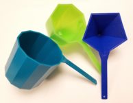
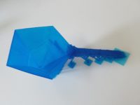
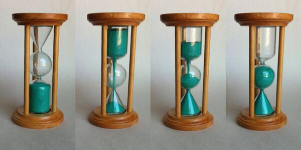
Well, in fact there is: the so-called Archimedes hourglass, which I had seen people make and show at previous G4Gs, such as this beautiful example by Rod Bogart:

The reason this works is that Archimedes determined that the volume of a cylinder of unit radius and two units height is equal to the sum of the volumes of a sphere of unit radius and a cone of unit base radius and two units height. Is there some variation on that which could be interesting? To try to find something like that, maybe we should look at how the proof of that fact goes.

But first, those occurrences of “two” seem a bit out of place. It seems a much more natural statement to say that the volume of a cylinder of unit radius and unit height is equal to the sum of of the volumes of a hemisphere of unit radius and a cone of unit base radius and unit height. And indeed, that statement has a simple and natural justification. Archimedes looked at it differently, but the 5th century Chinese mathematician Zu Gengzhi elucidated a principle (not rediscovered in Western mathematics until Bonaventura Cavalieri in the 17th century, and so sometimes called the “Cavalieri Principle”) that makes this straightforward, the Gengzhi Principle:

If the cross-sectional areas of two solids along every plane parallel to a fixed plane are equal, the solids have equal volume.

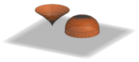
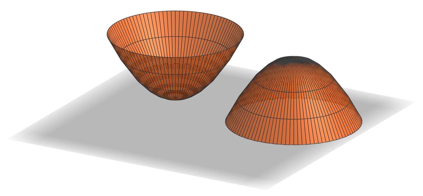
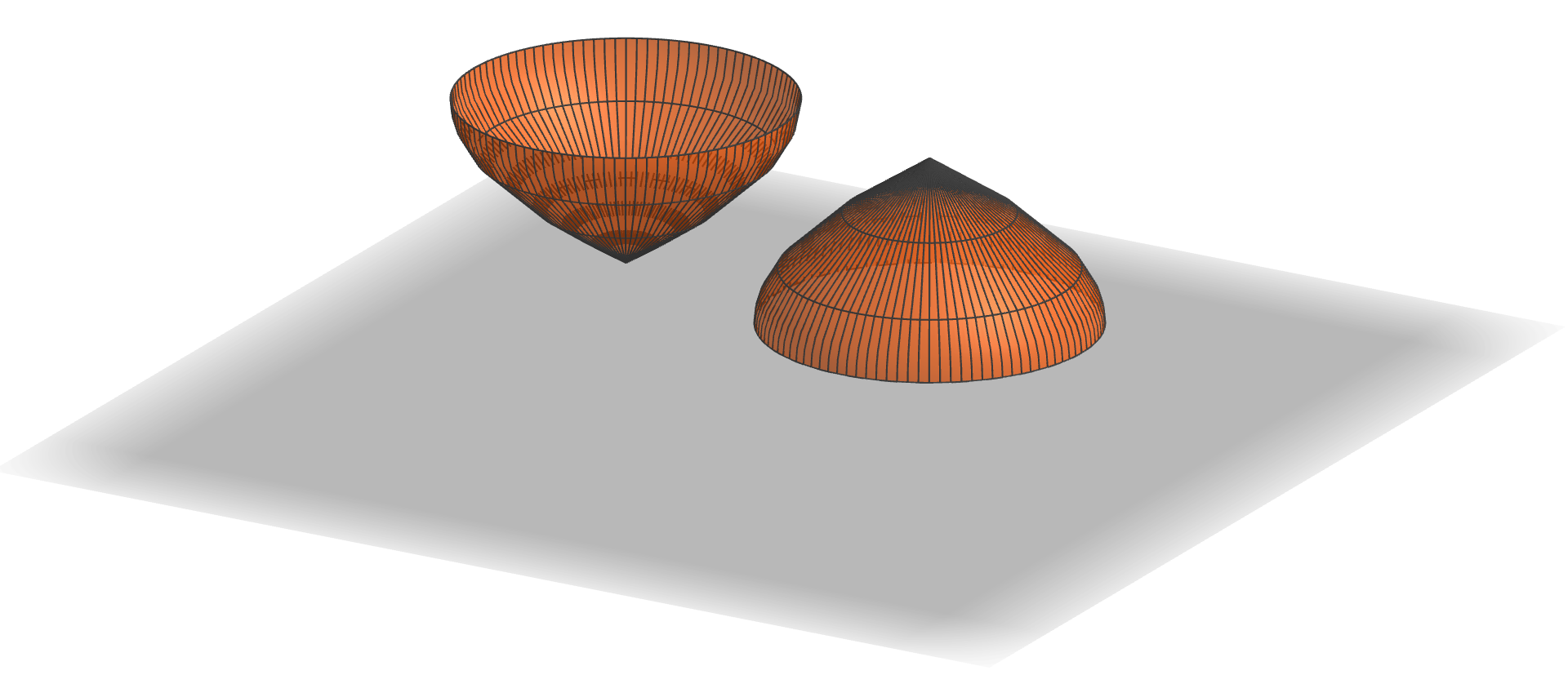
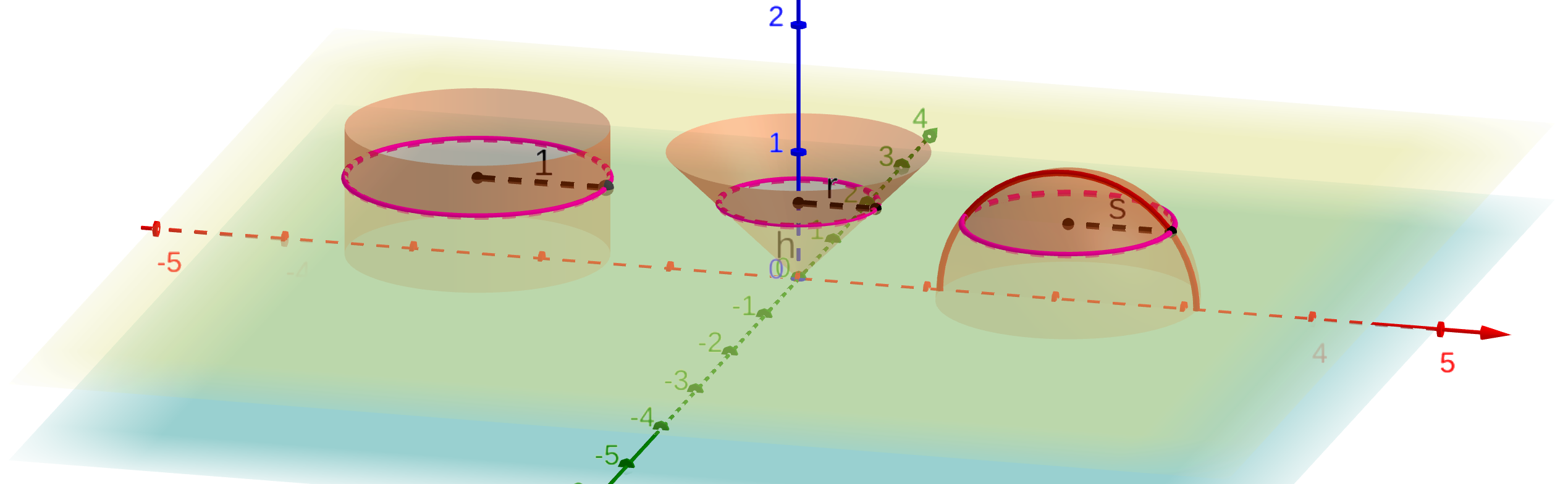
How does this apply to the cylinder, cone, and hemisphere? Let’s place them side-by-side this way:

The yellow plane is at height h above the xy plane (light blue), which is the common base of all three volumes (well, actually, we’ve placed the apex of the cone at z=0). The yellow plane cuts the cylinder in a circle with radius 1, the cone in a circle with radius r, and the hemisphere in a circle with radius s. Moreover, since the width of the cone increases linearly from 0 at the blue plane to 1 at a height of 1, r = h. And since the equation of the red semicircle (which is the vertical cross-section of the hemisphere) is h² + s² = 1, we have that s = √(1-h²).

Therefore, the area of the horizontal cross section (in the yellow plane) of the cylinder is π·1² = π, while the areas of the cross sections of the other two solids are πh² for the cone and π(√(1-h²))² = π(1-h²). The latter two obviously sum to the former, since h² + (1-h²) = 1. Since this holds for any plane parallel to the light blue plane, we conclude by the Gengzhi Principle that the volume of the cylinder is the sum of the other two, just as Archimedes established. (Living six centuries earlier than and half a world away from Gengzhi, Archimedes of course had to rely on other methods, considerably more complicated, to justify this relationship.)

But now, as we will see in the next post, there is a great deal of flexibility in this proof of the Archimedes relationship — plenty to create an interesting G4G13 giveaway.

05 Apr

Boxtahedral Tower

Materials
763 6″ cardboard boxes: 232 each of 3 colors, 67 plain
2000 twist ties with beads
packing tape, roughly 1 mile

At last the day came for the installation of the Boxtahedral Tower at the Golden Gate Stem Fair. Here are all of the materials waiting to be set up. The build started off smoothly, with double rows of interlaced boxes quickly turning into trusses.         The struts came together to form the top peak, which by the end of the first day, had turned into a tetrahedron.        

On the second day of construction, the first of the so-called “unknown unknowns” hit. Here’s the construction at the end of that day:

Doesn’t look much different, does it? If you notice, though, it’s up on chairs now. When we simply tried to lift it up there at the beginning of the day, the horizontal members all but fell apart. When we tried to figure out why — after all, the struts had tested out pretty rigid in prototyping — we discovered that the packing tape barely stuck to the paint. It stuck very well to the untreated cardboard, but basically pulled right off of the paint. And it had never even occurred to test whether the tape stuck differently to painted or plain cardboard. So, to make a long day two short, it was spent solely on replacing the centers of horizontal struts with unpainted boxes, which took the tension beautifully, so that at the end of the day we were at the point we expected to be five minutes into the day.

The third day brought another unknown: the ceiling height. Turns out there was not five meters of height available in the venue. Fortunately, we could quickly scale down the bottom level by half, so that it became just the top half of an octahedron (which has a hexagonal footprint). So here’s a half-size triangular face waiting to be inserted under the tetrahedron (in place of one of the chairs). (Oh, and that means that the materials list above specifies more than was actually used, since it’s for the full tower as planned.)

And thanks to the cheerful diligent participation from all of the people pictured below, including the director of the Golden Gate STEM Fair, Marcus Wojtkowiak, (but also many others pictured and not pictured, too numerous to list), we completed the world-premiere installation of the Boxtahedral Tower.You can see it’s just about brushing the ceiling.

And here’s the obligatory shot looking up at the ceiling in the center of the structure. One of Studio Infinity’s finest constructions!

05 Apr

Crowdlearning

In addition to the main, planned build at the Golden Gate STEM Fair, and thanks to donations of materials from Primed Minds, there was also a do-it-yourself/take-home table at the STEM Fair. Participants produced such towers as this one:

However, this column isn’t mainly about the inquisitive fun that participants at the take-home table had, or the specific structures they built, or the interesting fact that you can build oct-tet type configurations with rectangular solids of any proportions (not just cubes), even though all of those things are interesting and worthwhile. It’s about the fact that you can always learn something from anyone, and that inspiration can strike anywhere.

I ran headfirst into these facts after I had returned to Studio Infinity headquarters from the STEM Fair and was putting away all the materials from the take-home table that nobody had claimed. Fortunately, I had waited a day to do this and was feeling refreshed and less inclined to just toss materials in the garbage bin. When I opened up one of the construction units that a visitor to the table had made, my first reaction was “Oh, this person didn’t quite understand how to put the unit together.” But my second reaction was “Oh, this person put the unit together in a simpler, faster way than we were suggesting!” So the rest of this post is the recipe for “Boxtets v2.0: The Wisdom of Crowds.” (Compare to the original recipe for Boxtets.)

Boxtet v2.0
unassembled cardboard box
4 twist ties or pipe cleaners

Of course, the particular innovation documented here must have stemmed from some specific visitor or group of visitors working together; but since I have no way of knowing the particulars, I just have to credit the discovery to the “crowd.”

Begin to assemble the cardboard box as normal, but before closing up the bottom, insert two pipe cleaners each protruding from two corners. Select corners so that there is a reasonable length of the pipe cleaner protruding from the box at each end. Then seal up the bottom as normal. Pull the pipe cleaners taut on the inside, so an equal amount protrudes at each end. Similarly, before sealing the top, insert two pipe cleaners each protruding from two corners. Seal the box up the rest of the way, and you have a Boxtet, constructed much more quickly than before.


One caveat about using these Boxtets: if you only attach to one end of a given internal pipe cleaner, that pipe cleaner could pull out from its other end. So you may want to connect it to a wooden bead on the outside of the box if it’s not connected to anything else. Any pipe cleaner which is connected to other Boxtets on both ends will be fine.

05 Apr

GGSF: Prep

A brief post about the importance of prepping and prototyping for a build, and a couple of things that came up in the prep for the Golden Gate STEM Fair event. First, there’s just the sheer volume of supplies for such an event. Here are lots of beads getting outfitted with twist ties, for example. Also, to make the sculpture look more attractive, the boxes needed to be painted, 300 each of three colors.

More importantly, you get a feel for the structural characteristics of your medium. Experience (and physics) show that some sagging of horizontal members in a structure like this is inevitable, but full-scale stress tests like this one revealed that the stiffness of the struts varied greatly depending on their orientation. With the top row of boxes vertical as shown, the sag was acceptable, but rotated 90° (about the long axis), the struts were far less rigid, with all of the edge-to-edge joints acting like hinges.

As a result, additional methods of attaching boxes edge to edge needed to be developed. First, the boxes could be assembled with two flaps still sticking out, like so:. That way the flaps could be taped to the adjacent boxes in the structure. The cubes are still positioned edge-to-edge, just linked more securely. And second, for making the double diagonal row of boxes along the middle of each truss, we could just slide the flaps from adjacent boxes into each other, like this: These changes produced very rigid struts, as you can see in the picture below, leading to high confidence going into the Golden Gate STEM Fair build.

05 Apr

GGSF: Calculations

This post just takes care of some of the calculations used in planning the Golden Gate STEM Fair event. First, the plan was to make the structure shown at the right: a regular tetrahedron on top of a regular octahedron. Moreover, the resulting construction was intended to be five meters tall. Hence, the question arises: How long should each truss of the structure be to achieve the desired height?

It’s easier to work in the other direction. Assume that each edge of the structure has length s; how tall is the overall structure? Let’s start with the tetrahedron part. The apex lies directly over the center of the equilateral triangular base of the tetrahedron. We know the side length of the that triangle is s so we use the formula relating the radius r of a circle and the side of an inscribed regular polygon: s = 2rsin τ/2n, where n is the number of sides of the regular polygon, in this case three (and τ is the full circle constant, equal to 2π). So we get sin τ/6 = sin 60°, which is √3/2, from which we conclude that s = √3 r or r = s/√3.

Now we have a right triangle from the base of the tetrahedron to its apex, from which we conclude that h = √(s²-s²/3) = s√2/√3.

That tells us the height of the tetrahedron on top, but what about the octahedral base? We could go through a similar sort of calculation, albeit more involved, but we can also save ourselves a lot of trouble by noticing that if we lay the whole structure down on its side, we get a tetrahedron nestled up against the side of an octahedron, which makes it clear that the regular octahedron and regular tetrahedron are the same height. Thus, the tower overall has height s2√2/√3. Solving this for s when the height is 500 centimeters yields about 306 cm. And since we’re using boxes measured in inches and a foot is about 30cm, it’s easiest to think of that as 10 feet. So the moral of the story is that we need each truss to be ten feet long.

How many boxes will that take? Well, the boxes are 6 inches on a side, but they lie on the trusses along a face diagonal, which is 6√2 or about 8.5″. So we need the trusses to be 120/8.5 = 14.1 boxes long, or say 15 boxes long to be on the safe side. Extending a truss by one unit typically takes four boxes (one on the top and bottom and two in the middle), so that’s roughly 60 boxes per truss. With 15 trusses in the whole structure (just by counting in the diagram at the top), we can estimate about 900 boxes in the entire structure. And we know that’s an overestimate, because the trusses overlap each other where they join. So it’s a safe number to use for planning.