Deltahedral Torus?
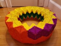
Here’s a torus built from equilateral-triangle Geometiles that I used as a prop for an undergraduate talk at Harvard University in the Fall semester of 2018.
Read More

Here’s a torus built from equilateral-triangle Geometiles that I used as a prop for an undergraduate talk at Harvard University in the Fall semester of 2018.
Read More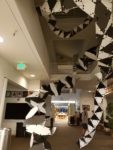
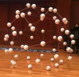
This is a placeholder post for pictures of an installation I led on 2018 Oct 21 at the Mathematical Sciences Research Institute, entitled “Tetrahelix”. It consisted of a double helix, one strand of which was composed entirely of regular tetrahedra connected face-to-face (such compounds can reach any point in space and come arbitrarily close to closing in a loop but can never make a mathematically perfect loop), and the other strand of which was the combinatorial dual of the first, realized by a geometric structure that can only be thought of as a “polyhedron” in a relaxed way. When I get a chance, I will post the construction techniques and math behind this installation.
Read More
As one of their projects, students in my class this fall wrote about something they’ve seen that sparked mathematical questions and ideas for them. The series of posts below shows the results of their work. I hope you’ll enjoy seeing math through their eyes as much as I have.


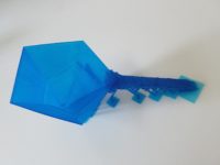
Here’s a a student-built snub dodecahedron that resulted from a session I led in July 2018 at The College of New Jersey. It uses the classic “marshmallow and toothpick” construction technique, just with styrofoam balls in place of the marshmallows and 1/8″ diameter dowels in place of the toothpicks.
Read More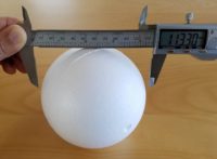
I recently purchased a large number of styrofoam balls as supplies for an upcoming build (about which I will post later). The plans for that build required the diameter of the styrofoam balls, to pretty high accuracy.
Read MoreHey, I have recently become problem editor for the undergraduate Math Horizons magazine of the Mathematical Association of America. So I’d love if you have problems/mathematical puzzles to submit to the column. The official submission blurb follows, and of course you will be credited in the Magazine.
The Playground features problems for students at the undergraduate and (challenging) high school levels. Problems or solutions (including more elegant or extended solutions to Carousel problems) should be submitted to MHproblems@maa.org or MHsolutions@maa.org, respectively. Paper submissions may be sent to Glen Whitney, ICERM, 121 South Main Street, Box E, 11th Floor, Providence, RI 02903 . Please include your name, email address, and school or institutional affiliation, and indicate if you are a student. If a problem has multiple parts, solutions for individual parts will be accepted. Unless otherwise stated, problems have been solved by their proposers.
This post contains the details of the claim made in “More Spherical Construction” that you can determine the side length of a spherical square from the ratio between the lengths of its diagonals. We’ll do this on a sphere of radius one; everything scales by a factor of the radius for a general sphere.
The advantage of working on a sphere of radius one is that then the side length is nothing other than the measure of the central angle (in radians) between two adjacent vertices of the square. Similarly, the diagonal is the central angle between opposite vertices of the square.
The easiest way to construct a square on the unit sphere is to place its center at the intersection of the sphere and the x-axis, and then choose a (positive) angle $\theta \leq \tau/4$ (where $\tau = 2\pi$ is the radian measure of a full circle) and place two vertices at plus or minus $\theta$ (from the square’s center) in the longitudinal direction and two vertices at plus or minus $\theta$ in the latitudinal direction. In spherical coordinates, the center is at $(1,0,\tau/4)$ and the four vertices are at $(1,-\theta,\tau/4), (1,\theta,\tau/4), (1,0,\tau/4-\theta), (1,0,\tau/4+\theta)$. For this square, the diagonal is obviously $2\theta$; it remains only to compute the side length of the square.
Using the great-circle distance formula on the two points $(1,\theta,\tau/4)$ and $(1,0,\tau/4-\theta)$ yields a side length of \[\arccos(\cos(\tau/4)\cos(\tau/4-\theta) + \sin(\tau/4)\sin(\tau/4-\theta)\cos(\theta)\;).\]
Since $\cos(\tau/4)$ is 0 and $\sin(\tau/4)$ is 1, this expression equals \[\arccos(\sin(\tau/4-\theta)\cos(\theta)).\]
And further, $\sin(\tau/4-\theta) = \cos(\theta)$, so the side length is just \[\arccos(\cos^2 \theta).\]
Therefore, the ratio of the diagonal to the side of the square is $2\theta/\arccos(\cos^2 \theta)$. Graphing this on the allowed interval $(0,\tau/4]$ for $\theta$ immediately demonstrates the claims made in the referring post: no value of the ratio is repeated for different values of $\theta$, so the ratio determines the diagonal (and side length) of the square; the maximum value is 2; and any value greater than $\sqrt2$ is achievable.
If you’d rather not rely on graphing software to extract these facts, but rather demonstrate them just from the formulas, here’s how you can proceed. The value 2 at $\theta=\tau/4$ comes from straight substitution. The value at 0 by substitution is the indeterminate 0/0, so we obtain the value by L’Hôpital’s rule: the derivative of the numerator is 2, but the derivative of the denominator is \[\frac{2\cos \theta}{\sqrt{1+\cos^2\theta}},\] so the diagonal-side ratio has the limiting value $\sqrt2$ at $\theta =0$. Finally, we need to show that the ratio is monotone increasing on the interval of interest. By the quotient rule, this is equivalent to showing that on this interval \[\arccos(\cos^2\theta) > \frac{2\theta\cos\theta}{\sqrt{1+\cos^2\theta}}.\] Both sides are 0 at $\theta=0$, so we can take derivatives one more time; the derivative of the left-hand side is of course $2\cos\theta(1+\cos^2\theta)^{-1/2}$ again, which on this interval is always larger than the derivative of the right-hand side, namely $2\cos\theta(1+\cos^2\theta)^{-1/2} – 2\theta\sin\theta(1+\cos^2\theta)^{-3/2}$. So the left-hand side is also always larger than the right hand side, i.e., the derivative of the diagonal-side ratio is positive on this interval.
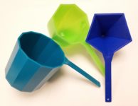
One might think that having produced prototypes of the Gengzhi Goblets, our work is just about done to produce sufficient quantity (roughly 300 of each) to serve as G4G13 giveaways. The question comes down to materials and expense. If the Gengzhi Goblets are actually to be used as measuring cups, then they need to be made from a food-safe material.
Read MoreTo compute the height $H$ of the Gengzhi Goblets so that the 13-gon prism has volume 1 cup ≈ 236 cubic centimeters, and the radius of the pentagon goblet so that its maximum cross section is the same as the 13-gon (and hence its volume is exactly one quarter as large, or 59 cc):
Note that we assume that the height of the 13-gon prism will equal the distance from one vertex to the midpoint of the opposite side. Referring to the Wikipedia page on regular polygons for formulas, that is to say that the height will equal the circumradius plus the apothem. Now the volume $V$ of the 13-gon prism is the height times the area of the 13-gon, which is $\frac{13}2r^2\sin(\tau/13)$. (As usual we use $\tau$ for the radian measure of a full circle, namely $2\pi$, as it makes most formulas clearer in terms of fractions of circles.) Combining these two observations, we get that
\[V = \frac{13}2r^2\sin(\tau/13)(r + r\cos(\tau/26)) = r^3(\frac{13}2\sin(\tau/13)(1+\cos(\tau/26))).\]
Setting $V$ equal to 236 and solving for $r_{13} = r$, we get $r_{13} = \sqrt[3]{472/(13\sin(\tau/13)(1+\cos(\tau/26))} \approx 3.41$cm. The height is then $H = r_{13}(1+\cos(\tau/26)) \approx 6.72$cm.
Finally, to find the radius $r_5$ such that pentagon with circumradius $r_5$ has the same area as the 13-gon with circumradius $r_{13}$, we set the respective area formulas equal and solve: $r_5 = r_{13}\sqrt{13\sin(\tau/13)/5\sin(\tau/5)} \approx 3.84$cm.
By exploring the theory, the following shapes arose as a natural G4G13 giveaway: a regular 13-gon prism, a cup with octagonal cross sections whose octagon sides scaled with height as √(1-h³), and a cup with pentagonal cross sections with sides scaling as h3/2.
Read More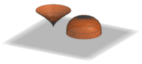
So I had zeroed in on the proof of the Archimedean volume relationship as the source of my giveaway for G4G13. But how to create an interesting variation?
The first thing to notice is that the function of h that appears in the proof in the cross-sectional area of of the cone, namely h², could be any function f(h) whatsoever, and the proof would be just as valid — solids where the cross-sectional areas went as f(h) and 1 – f(h) would have volumes that add up to that of a cylinder.
So, in some sense the simplest example would be solids with cross-sectional area going as h and 1-h. What would they look like? Well, they would correspond to radii at height h of √h and √(1-h). In other words, they would be solids of revolution about the z-axis of the graphs of √h and √(1-h), like so:
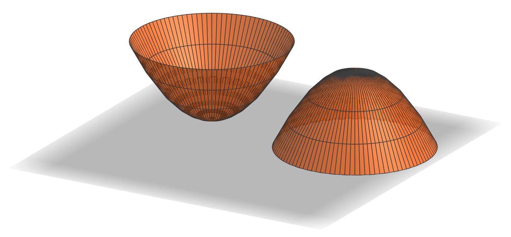
First, these two objects look identical (just one is upside down as compared to the other). But that’s no surprise: as h goes from 0 to 1, 1-h goes from 1 to 0, and at the same rate. But that means that each one must have half the volume of the corresponding cylinder. And further, since the graph of √h is a parabola (on its side), these objects are paraboloids. So we’ve established
the paraboloid of unit height and radius has half the volume of the cylinder with unit height and radius,
which is kind of cool already. So should this be the giveaway?
It was time to figure out what the giveaway items would actually be. Since the principle was about volumes, they needed to be something which was related to volume, but I didn’t want to create another hourglass. So the obvious answer was that they should be measuring cups. And that decision suggested that I shouldn’t use f(h) = h, since two identical measuring cups would be boring.
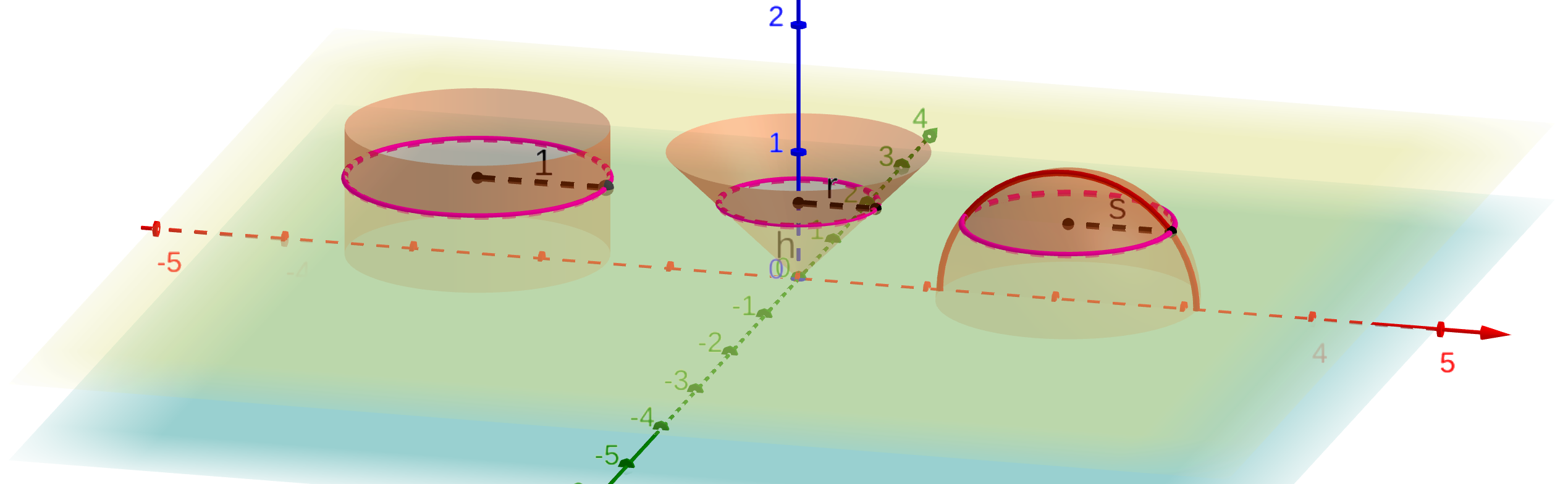
Since I’d now looked at h and h², the natural next choice would be h³. Here’s what the corresponding solids look like:

Those look pretty interesting. So if I used these shapes, what would the volumes be? Now it’s by far easiest to go ahead and use that late-17th-century invention, calculus. The volume of the “pointy” shape should be $\int_0^1 \pi h^3 dh = \pi \left.h^4/4 \right|_0^1 = \pi/4$. In other words, if the cylinder were scaled to have a volume of one cup, say, then the pointy shape would have a volume of 1/4 cup and the rounded one would have a volume of 3/4 cup. That seemed pretty good: since most measuring cup sets do not include one with volume 3/4 cup, the resulting set might actually be useful.
But there’s another place you can vary the construction in the proof: the shape of the cross-sections. There’s no requirement that they be circles; you can scale any shape, and the overall volume will scale by the area of the largest cross section. (That’s the $\pi$ in the above formulas, namely the area of the top circle of the pointy shape or the bottom circle of the rounded one.) So I decided to use this flexibility to create one more link to G4G13: make the cross section of the “cylinder” be a regular 13-gon, the 3/4-cup measure a regular octagon, and the quarter-cup measure be a regular pentagon. These shapes echo the Fibonacci decomposition 13 = 8 + 5 where the mathematical free association began.
So although that brings us to the shapes that actually went into the G4G13 giveaway, this exploration wouldn’t be complete without emphasizing that there’s no reason f(h) has to be a power of h at all. We’re literally free to use any function at all, so long as it takes values between 0 and 1. In particular, why not try the most famous pair of functions that sum to 1 for the cross-sectional areas of the two cups, namely cos²(h) and sin²(h)? That would produce these shapes:
As in the first case, the shapes are identical, although in this case because of the identity sin(x) = cos(π/2 – x). So again, this shape has half the volume of the corresponding cylinder, even though it is clearly not a paraboloid (as you can see, for example, by the fact that it comes to a point at its apex; a paraboloid is smooth there). We could spend forever exploring different combinations of functions that would give Archimedes-like decompositions of a cylinder, but it’s time to turn attention to fabricating the G4G13 giveaway.

So it became time to decide on Studio Infinity’s giveaway at the 13th Gathering for Gardner (G4G13). By tradition, at least, it’s considered a plus for giveaways to connect with the number of the conference — 13 in this case. So this mathematical free association starts with the number 13.
What thoughts does 13 evoke? First and foremost, it’s a Fibonacci number, 13 = 8 + 5. So something about breaking something down by addition? Addition is so simple, what could an interesting giveaway to do with addition be like? What if it’s not just addition of numbers, but addition of something more involved? Like addition of volumes? Is there an interesting instance of volumes adding up nicely?
Well, in fact there is: the so-called Archimedes hourglass, which I had seen people make and show at previous G4Gs, such as this beautiful example by Rod Bogart:
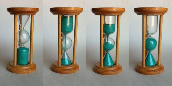
The reason this works is that Archimedes determined that the volume of a cylinder of unit radius and two units height is equal to the sum of the volumes of a sphere of unit radius and a cone of unit base radius and two units height. Is there some variation on that which could be interesting? To try to find something like that, maybe we should look at how the proof of that fact goes.
But first, those occurrences of “two” seem a bit out of place. It seems a much more natural statement to say that the volume of a cylinder of unit radius and unit height is equal to the sum of of the volumes of a hemisphere of unit radius and a cone of unit base radius and unit height. And indeed, that statement has a simple and natural justification. Archimedes looked at it differently, but the 5th century Chinese mathematician Zu Gengzhi elucidated a principle (not rediscovered in Western mathematics until Bonaventura Cavalieri in the 17th century, and so sometimes called the “Cavalieri Principle”) that makes this straightforward, the Gengzhi Principle:
If the cross-sectional areas of two solids along every plane parallel to a fixed plane are equal, the solids have equal volume.
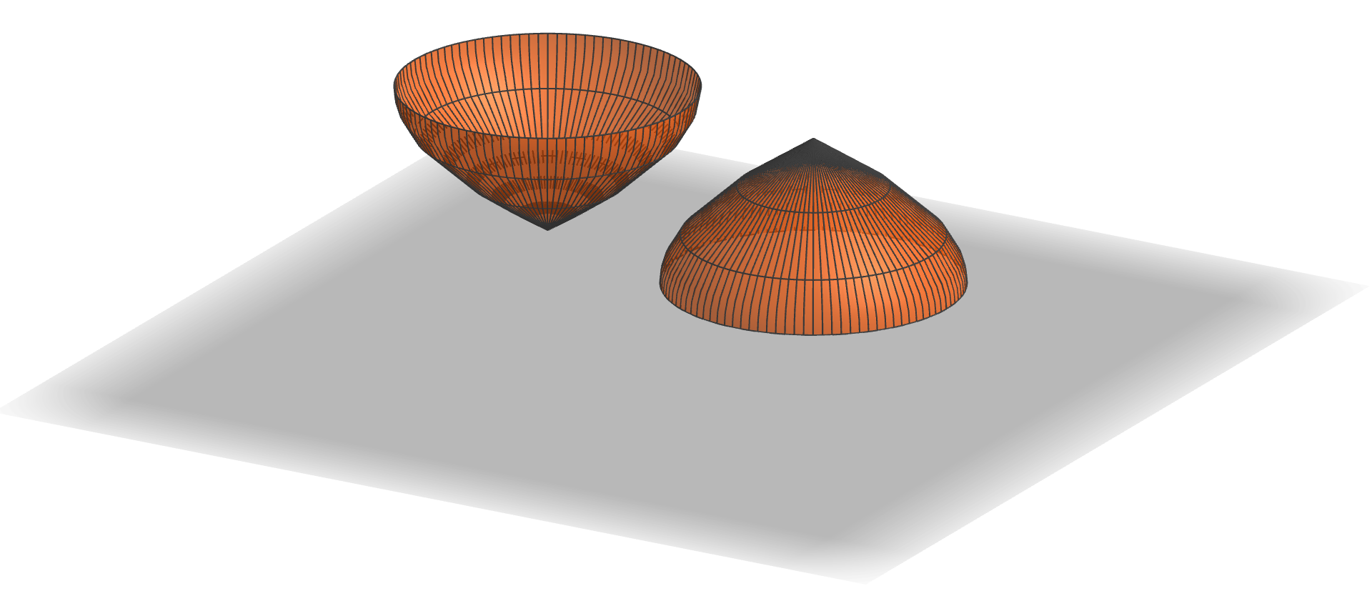
How does this apply to the cylinder, cone, and hemisphere? Let’s place them side-by-side this way:
The yellow plane is at height h above the x–y plane (light blue), which is the common base of all three volumes (well, actually, we’ve placed the apex of the cone at z=0). The yellow plane cuts the cylinder in a circle with radius 1, the cone in a circle with radius r, and the hemisphere in a circle with radius s. Moreover, since the width of the cone increases linearly from 0 at the blue plane to 1 at a height of 1, r = h. And since the equation of the red semicircle (which is the vertical cross-section of the hemisphere) is h² + s² = 1, we have that s = √(1-h²).
Therefore, the area of the horizontal cross section (in the yellow plane) of the cylinder is π·1² = π, while the areas of the cross sections of the other two solids are πh² for the cone and π(√(1-h²))² = π(1-h²). The latter two obviously sum to the former, since h² + (1-h²) = 1. Since this holds for any plane parallel to the light blue plane, we conclude by the Gengzhi Principle that the volume of the cylinder is the sum of the other two, just as Archimedes established. (Living six centuries earlier than and half a world away from Gengzhi, Archimedes of course had to rely on other methods, considerably more complicated, to justify this relationship.)
But now, as we will see in the next post, there is a great deal of flexibility in this proof of the Archimedes relationship — plenty to create an interesting G4G13 giveaway.