
Portion Prototyping
By exploring the theory, the following shapes arose as a natural G4G13 giveaway: a regular 13-gon prism, a cup with octagonal cross sections whose octagon sides scaled with height as √(1-h³), and a cup with pentagonal cross sections with sides scaling as h3/2.
The largest octagon and pentagon would be sized to have the same area as the 13-gon, which we saw would guarantee that the octagon cup (or “Gengzhi Goblet,” as we’re calling them) would have 3/4 the volume and the pentagon goblet would have 1/4 the volume. So we would scale the 13-gon goblet to have volume equal to that antiquated measure, 1 U.S. cup, or about 236 cubic centimeters.
You can actually do all of the above for any proportion of height of the measuring cups to diameter of the measuring cups. When I started the implementation phase, I was thinking one-to-one, so rather than height and radius of the cups being equal as in the design phase, I produced cups whose height and diameter are equal. So they all ended up taller and thinner than the images in the design post, but that doesn’t affect the intrinsic volume relationships.
To create prototypes, I had access to an XYZprinting Nobel 1.0a SLA 3D printer. The software for this printer likes to import STL files. To convert the mathematical concepts generated in the design phase to STL files, I chose to use the free, open-source software package SageMath. First, I needed to calculate the height of all three cups and the (maximum) radius of each cup. The maximum radii differ because we want the area of the largest cross section of each of the cups to be identical, but the relation between radius and area differs slightly for each of a pentagon, octagon, and 13-gon. You can see the details of those calculations in a separate post. In any case, once the height H and pentagon radius r5 (say) have been computed, here’s how you get an STL file for the pentagon cup. We need a parametric surface whose radius goes as h3/2. In SageMath we execute def r(h): return r5*h^(3/2). To get the cup, we define def Px(h,t): return r(h)*cos(t), def Py(h,t): return r(h)*sin(t), and def Pz(h, t): return H*h. Since (cos t, sin t) parametrizes a unit circle as t varies from 0 to τ = 2π, Px and Py parametrize a circle of radius r(h), and Pz just stretches the height out to the desired value. Now, you might object that this parametrization yields a solid with circular cross sections, and you would be right; but we recover the desired pentagonal cross-sections by deliberately limiting the number of mesh points that SageMath will use to produce its plot:

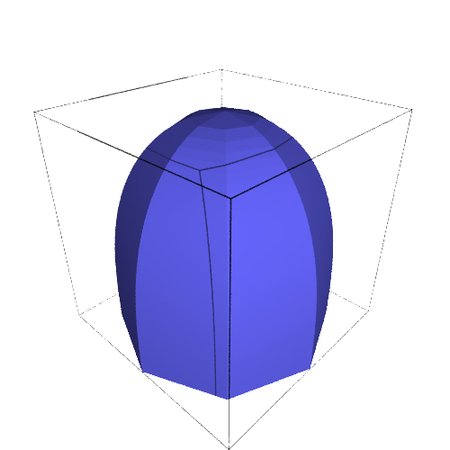
pent = parametric_plot3d((Px, Py, Pz), (0,1), (0, tau), plot_points=[40,6]) followed by pent.show() produces the following.
(It might seem fishy that you use 6 points in the t-direction of the mesh to get 5-sided figures, but note that t=0 and t=τ, the first and sixth points, actually represent identical points because of the τ-periodicity of the circle parametrization.)
The other two shapes are similar, although you have to be careful with the prism; since it has a corner, you can arrange that as h goes from 0 to 1/2, r goes from 0 to r13 while z stays put at 0, and as h goes from 1/2 to 1, r stays put at r13 and h goes from 0 to H. In SageMath, this looks like def r(h): return min(r13,2*h*r_13) and def Fz(h, t): return max(0, 2*(h-0.5)*H). Here are images of the resulting plots:

To get these plots out of SageMath as STL files, the commands look like:
p_stl = pent.stl_ascii_string()
pfile = open('/path/to/your/file','w')
pfile.write(p_stl)
pfile.close()
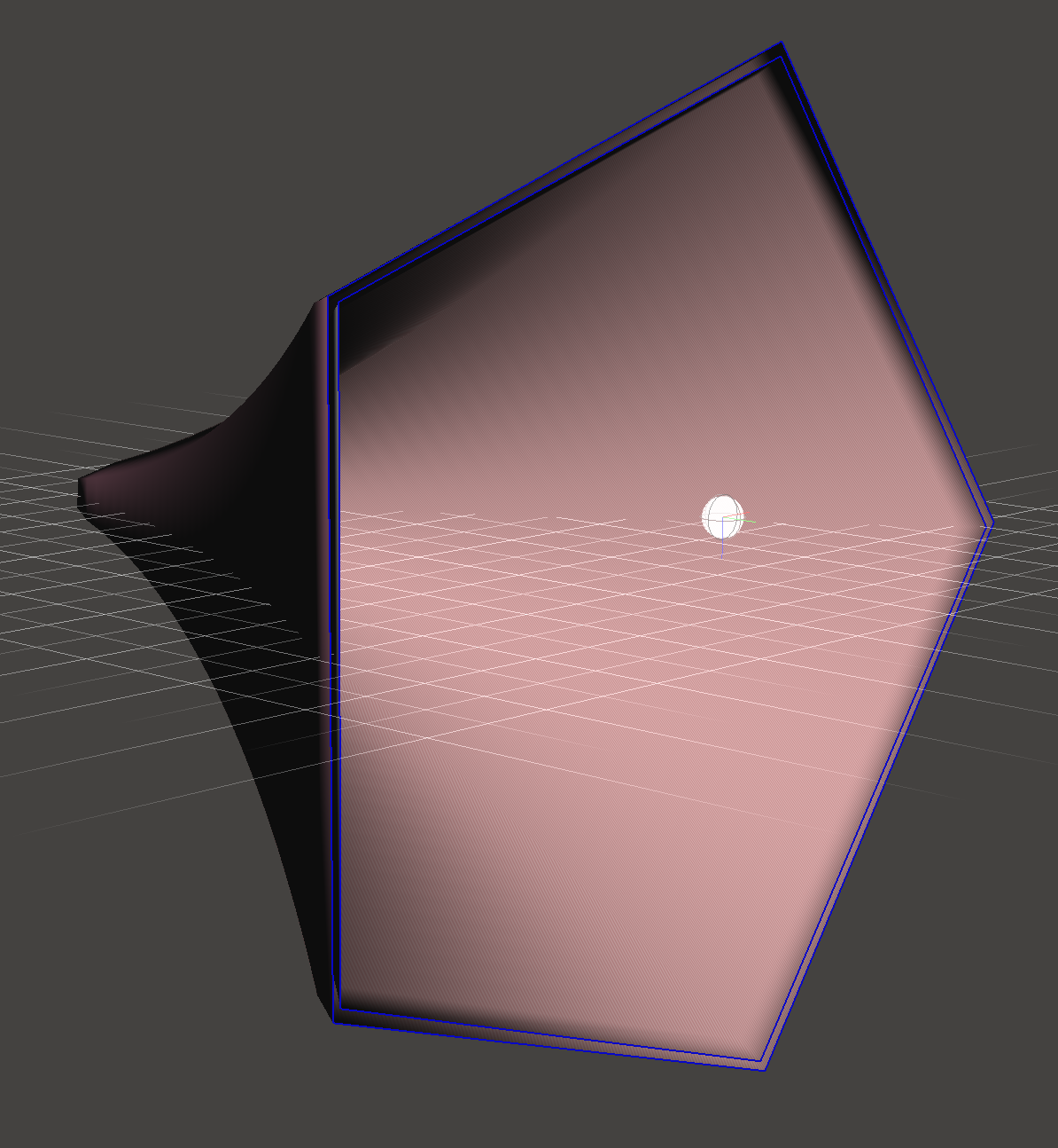
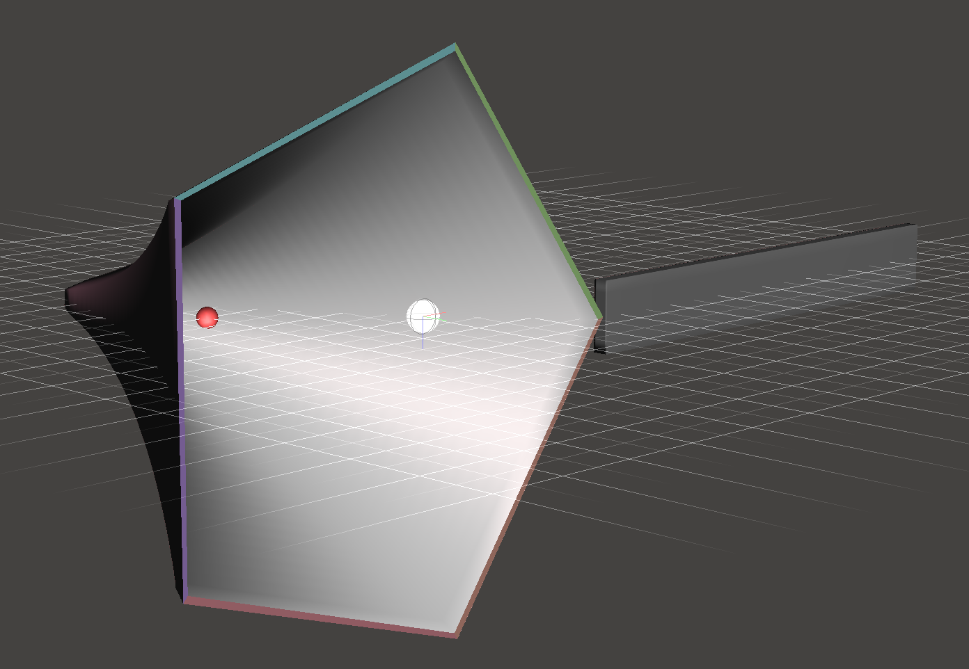
Unfortunately, these STL files are not ready to print directly; they consist of just a “membrane” with no real thickness. To make something printable, we need to thicken them up and add handles and labels and such. There are many possible packages one might use to do that; I chose MeshMixer, a free but closed-source program from AutoDesk. MeshMixer has a tool called “Offset” (that is only available when you have a surface selected) that is tailor-made for turning a surface into a thick wall. However, to keep the top lip of the cup flat, you should first mirror the cup as in the left picture below, then use an Offset of 2mm in the “Normal” direction, and slice off half of the result to get something looking like the right-hand picture below.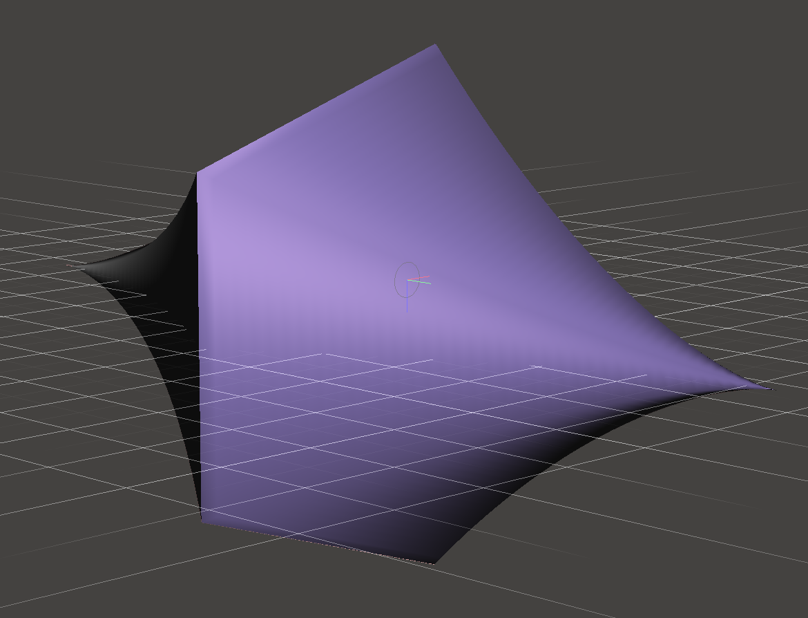
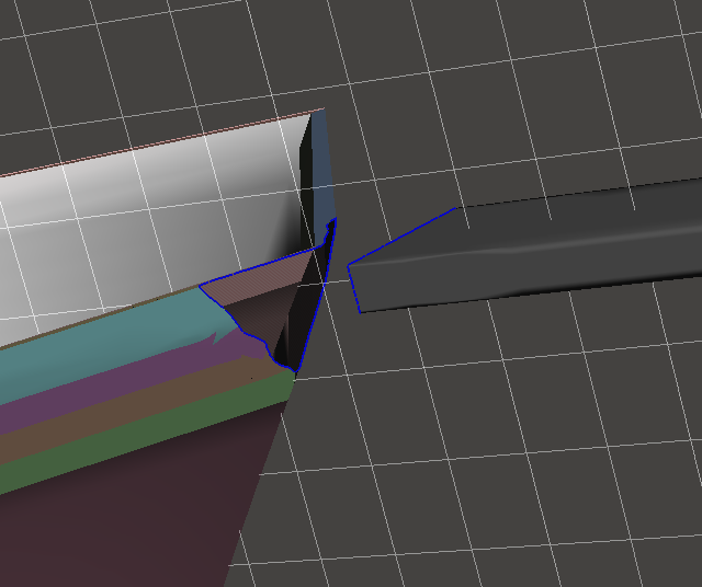
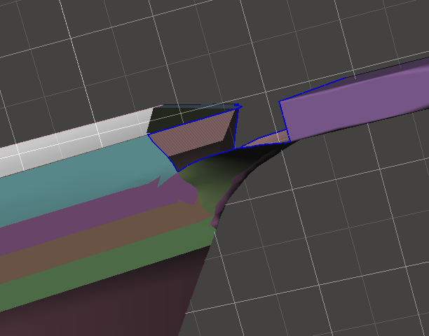
You can then use the rectangular solid primitive to add a handle. It’s floating separate from the cup, so you have to cut open some apertures on the cup and handle, and then use the “Bridge” and/or “Erase & Fill” tools to join them.
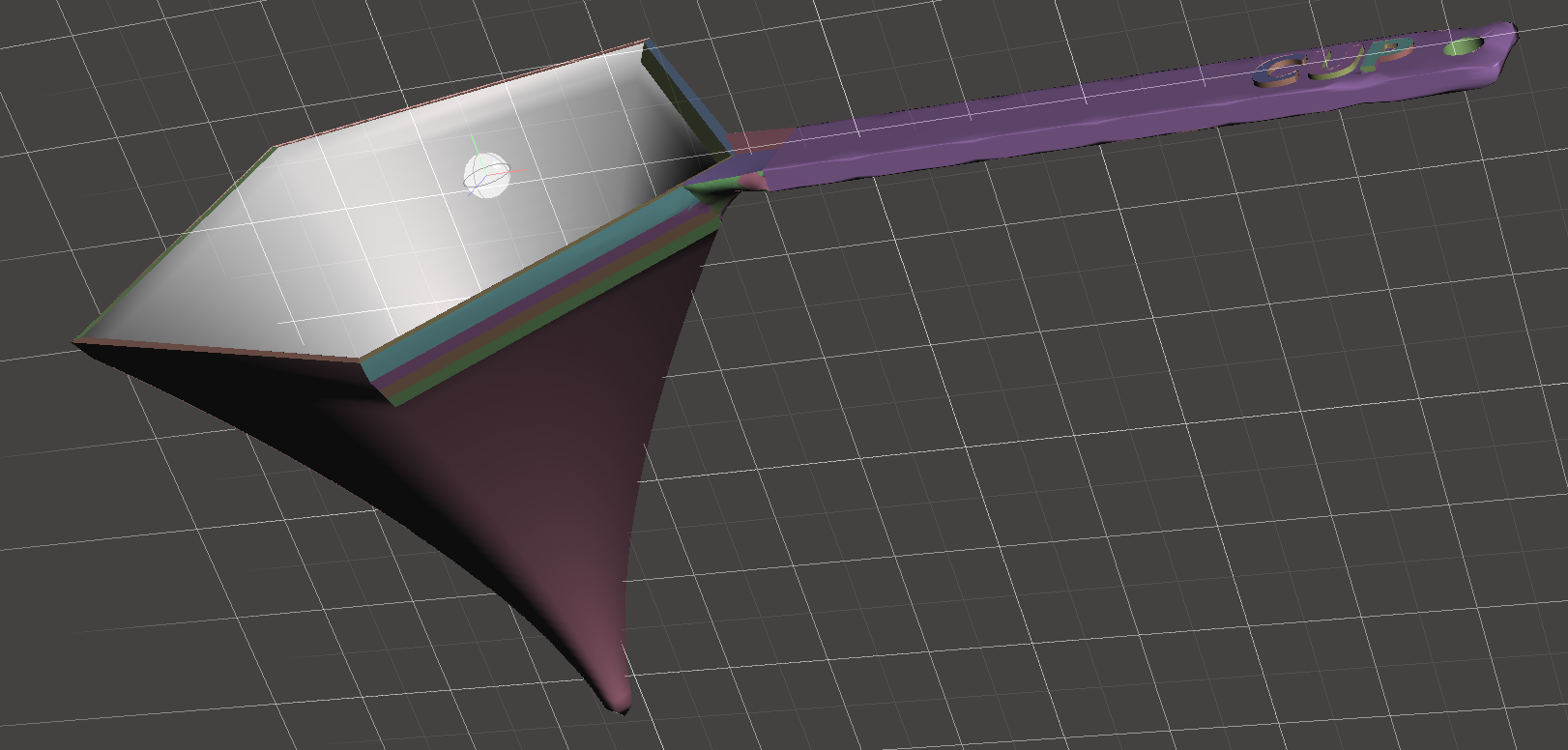
Finally, once the handle is fully attached, you can use MeshMixer’s letter embossing facility to add the caption on the handle. (I’ve also used some Boolean operations to cut a hole in the end of the handle.)
Or, here it is in live 3D:
(In case you’re interested, here are direct links to all three STL files: quarter cup, 3/4 cup, one cup.)
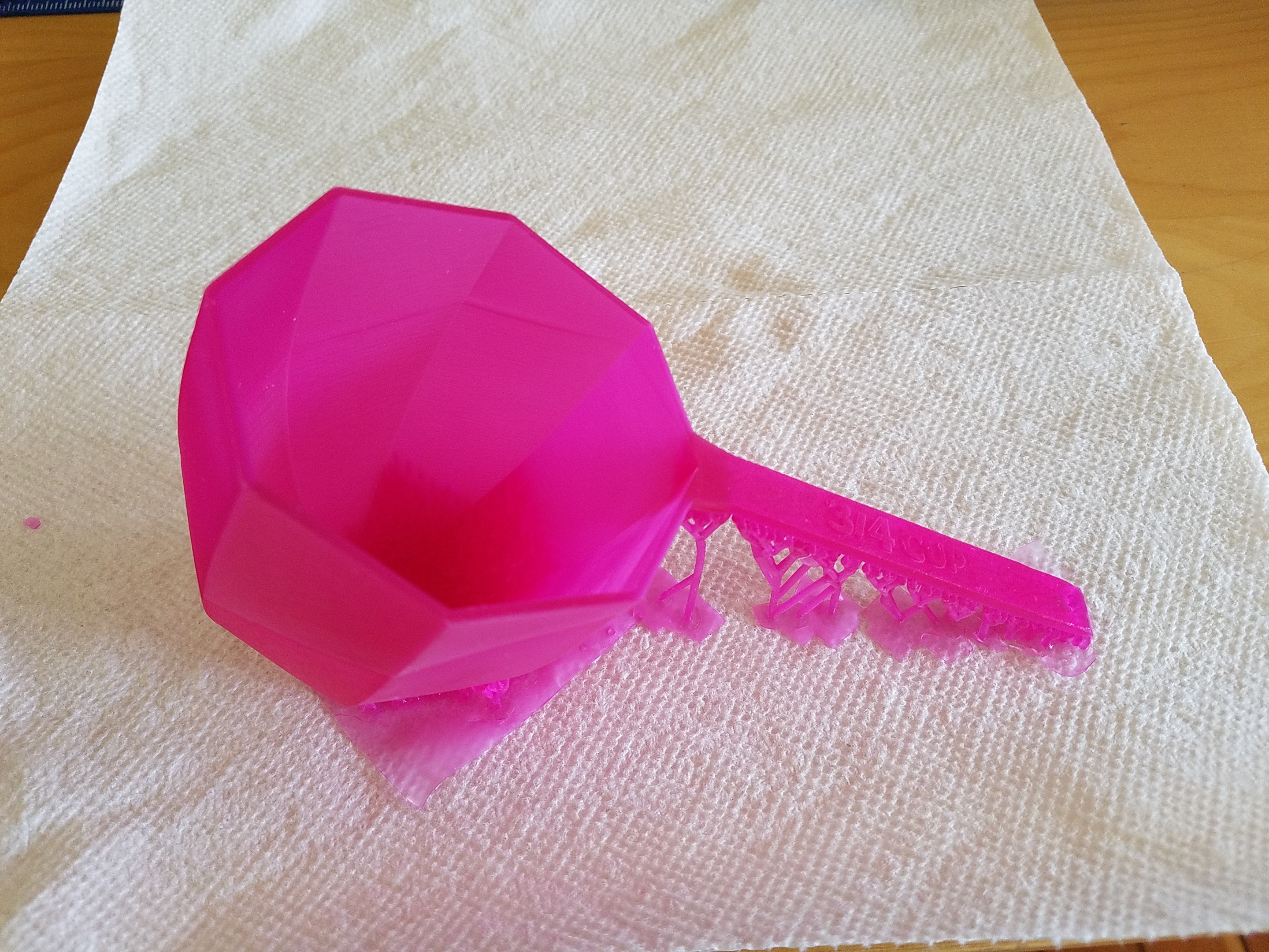
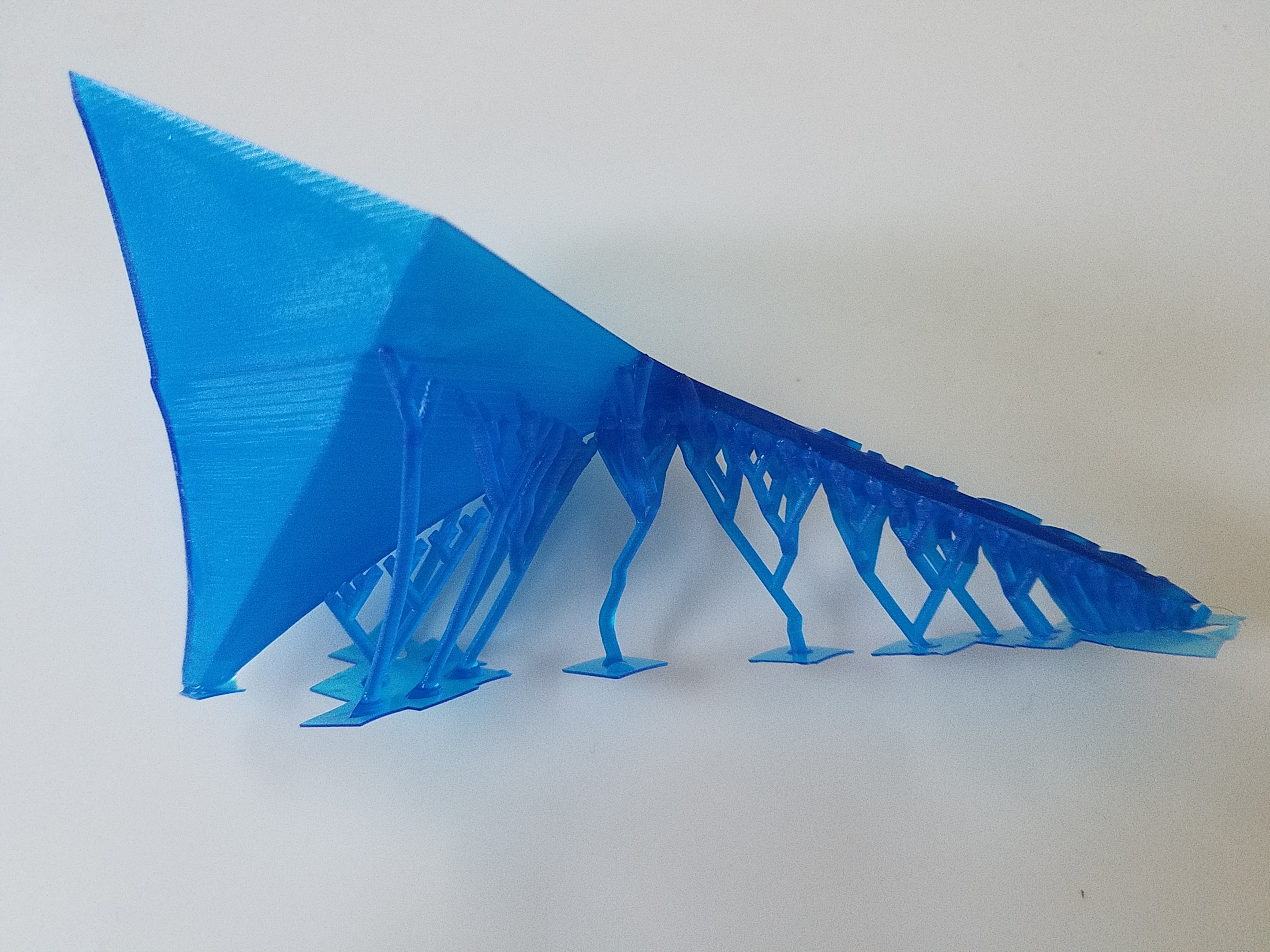
Now you could transfer the resulting STL to XYZprinting’s software, but in my experience the support-generation code in their software is not as reliable as that in MeshMixer. So under Analyze, use the “Overhangs” tool to generate supports. Now transfer to XYZprinting and have it “slice” and print the model to get your prototype!