23 Apr

Pythagoras Cubed

I was recently invited at the last minute to lead a mathematical construction for a seminar for math majors at Loyola Marymount University. The hope was to create something physical connected with one of the topics in the course, which linked the history of mathematics with various unsolved problems, among other things. Since there had been a fair amount of discussion about the Pythagorean Theorem, we settled on the following construction that demonstrates an interesting and less-familiar related phenomenon in three dimensions.

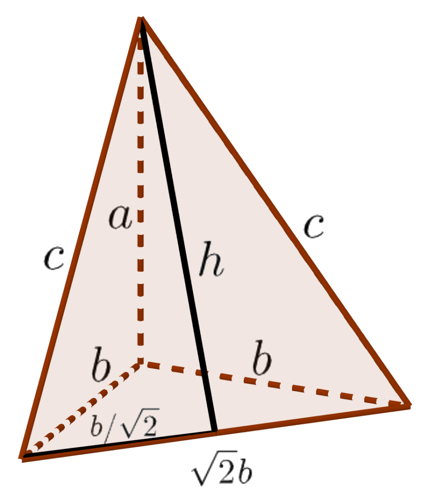
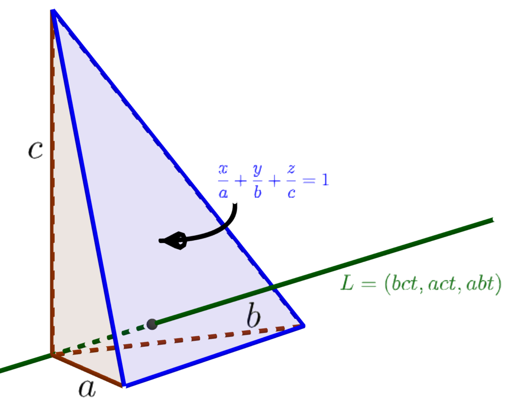
Given any three lengths, you can build a tetrahedron with a vertex where three right angles meet, and the lengths of the three edges meeting there are as given. (Basically, just cut off the positive coordinate axes to the three given lengths and join the resulting endpoints with a triangle.) Such a tetrahedron is called a “right tetrahedron” and those three initial lengths are called the “legs.” The following construction (erecting a prism on each face whose height is the same as the area of the face) can be performed with any lengths for the legs, but all of the calculations below are done for legs √6, √19, and √30 (which have the pleasant property that the sides of the fourth tetrahedron face are then 5, 6, and 7, as shown in the diagram to the right). To create a human-sized result, I used a decimeter as the length unit; if you wanted to make this into a tabletop-sized construction, you could scale it down by a factor of four or five — but note that when scaling down the edge rod lengths (as opposed to the altitude lengths) you need to add one centimeter, divide by your scale factor, and subtract off the one centimeter again, to allow for the extra length created by the connectors.

MaterialsTools
About 30 1/8″ diameter rods, at least 147 cm long (5′ suffices), for example wooden dowels or fiberglass rodsMeasuring tape
About 90 custom connector clips (STL file, or OpenSCAD file if you need to tweak them)Meter sticks
Three sheets of foam core, at least 70 cm by 50 cm (30″ by 20″ suffices)Cutting pliers or small saw (for cutting rods)
Plastic wrap (ideally four colors of industrial-size rolls)Box cutter (for foam core)
At least 225 liters of loose fill material (e.g. packing peanuts); 9 cu. ft. sufficesScissors
If rods expand after cuts:
Optional: thick paper or cardstock for temporary lidsGripping pliers
Drill slightly larger than 1/8″ (e.g. 9/64″)

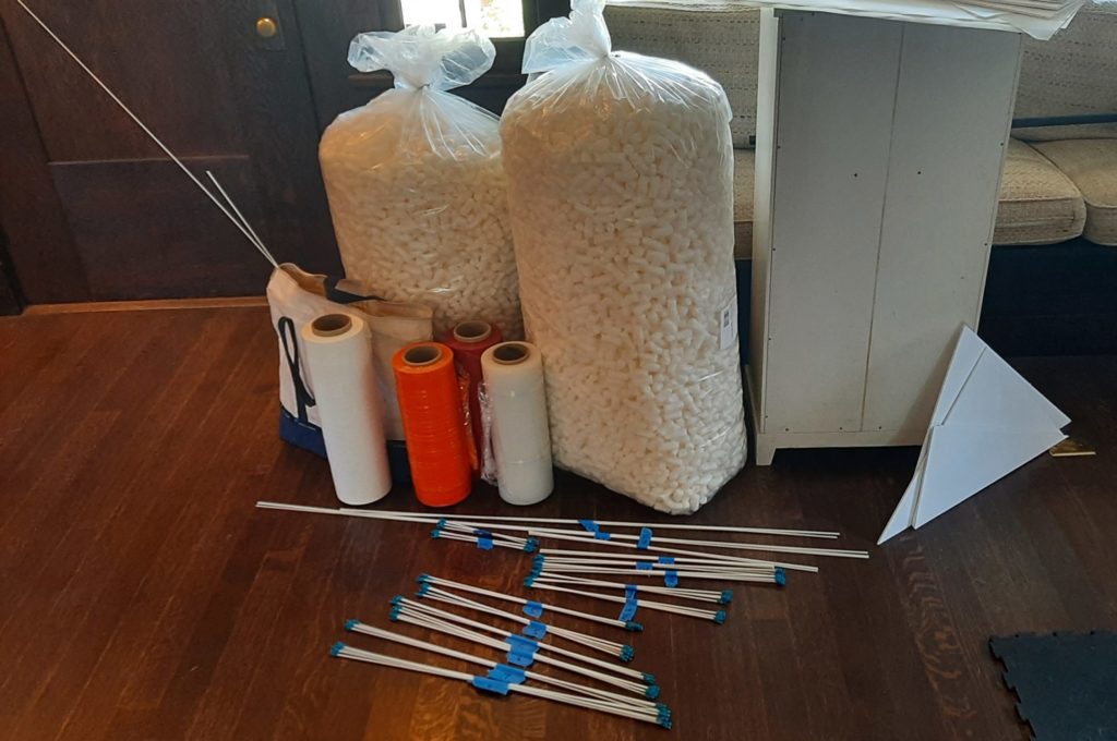
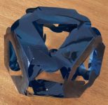
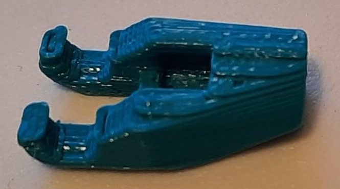
Assemble all of the needed materials and tools, and fabricate the connectors per the supplied STL file. [vrm360 model_url=”http://studioinfinity.org/wp-content/uploads/2022/04/DowelSnapV6.stl”]

A row of freshly printed connectors before
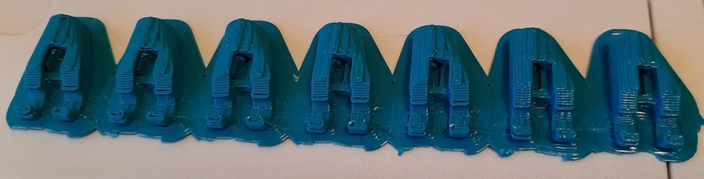
removing the support material
One finished connector ready for use
Length (cm)QuantityFor
1473altitude D
119.43altitude C
699edges of C and D
67.13altitude B
598edges of B and D
53.87edges of B and C
53.43altitude A
498edges of A and D
42.66edges of A and C
23.56edges of A and B

Then begin by cutting lengths of your edge rods as in the table to the right:

Because the vendor-supplied cut ends of the edge material will likely be more uniform than your hand-made cuts, especially if you choose to use cutting pliers, try to preserve as many of the manufactured ends as possible when cutting.

Next, slide connectors onto both ends of each of the rods designated for “edges” in the table above. With the fiberglass rods I was using, the ends I hand-cut with pliers deformed and expanded, so I had to ream the holes of the connectors for these ends out to 9/64 inch by hand-twisting a drill (held by gripping pliers) into the holes.

Cut a foam-core bottom for each of the prisms, corresponding to the four faces of the central tetrahedron: the largest face D has edges 50, 60, and 70 centimeters (I just measured off 70 cm along one edge of a foam-core sheet, and then laid meter sticks down so that their corners met and they read off 50 and 60 cm respectively at the corner and marked point on the edge). The other three faces A, B, and C (in order of increasing area) are all right triangles, so I just measured the leg lengths along two adjacent sides of a sheet and then cut the resulting corner piece off. The lengths are: A – 24.5 and 43.6 cm, B – 24.5 and 54.8 cm, and C – 43.6 cm and 54.8 cm. (Note the edge lengths of the foam core faces are all 1 cm greater than the corresponding edge rods, because the connectors at each end of a rod add exactly 1 cm to their effective length.)

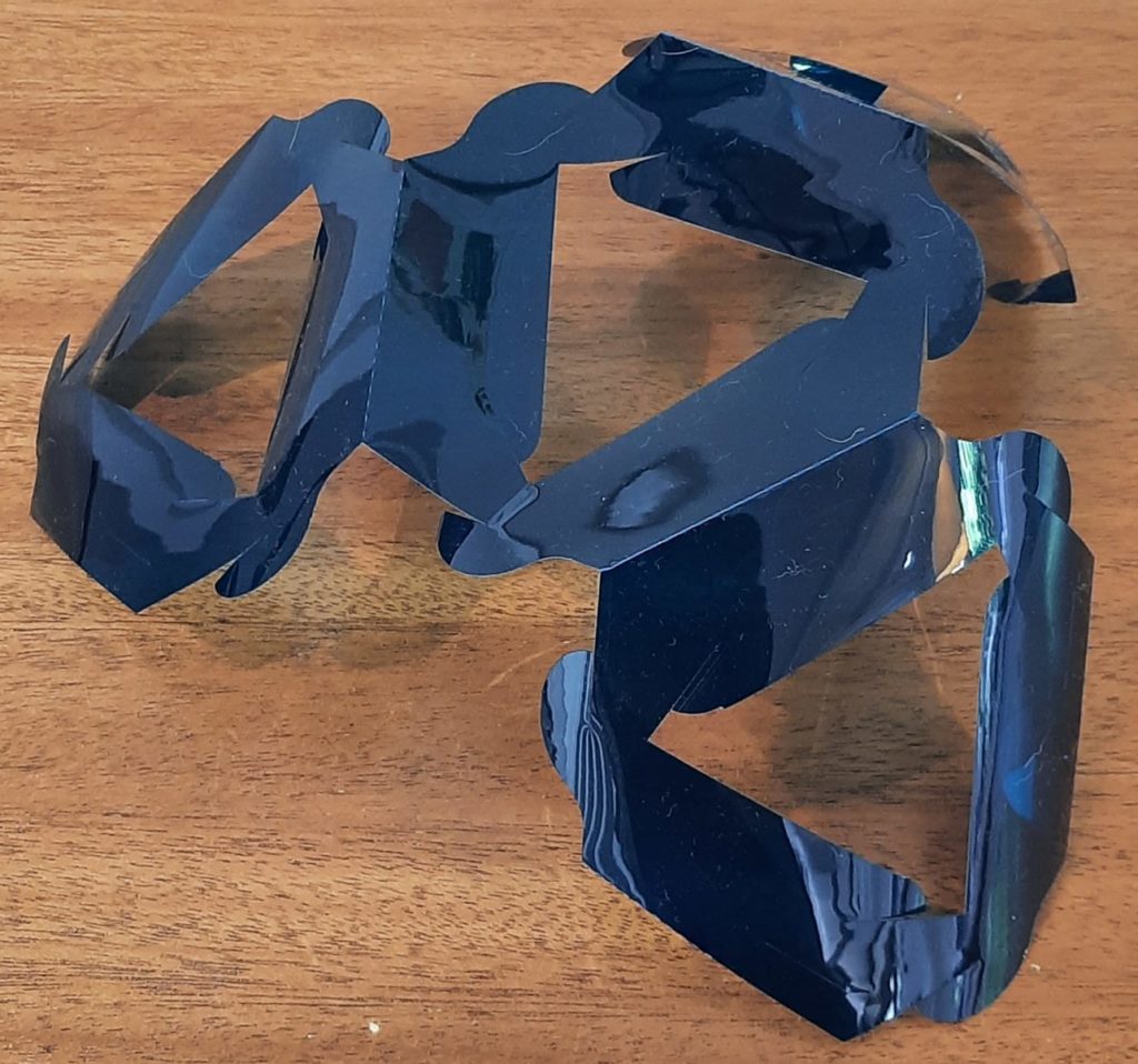
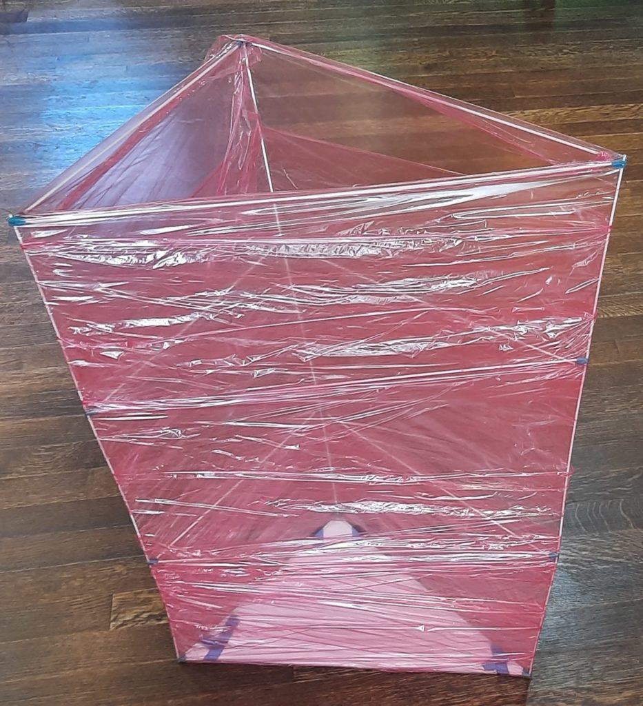
Assemble each of the prisms by clipping edges onto altitudes to form the desired cross section.

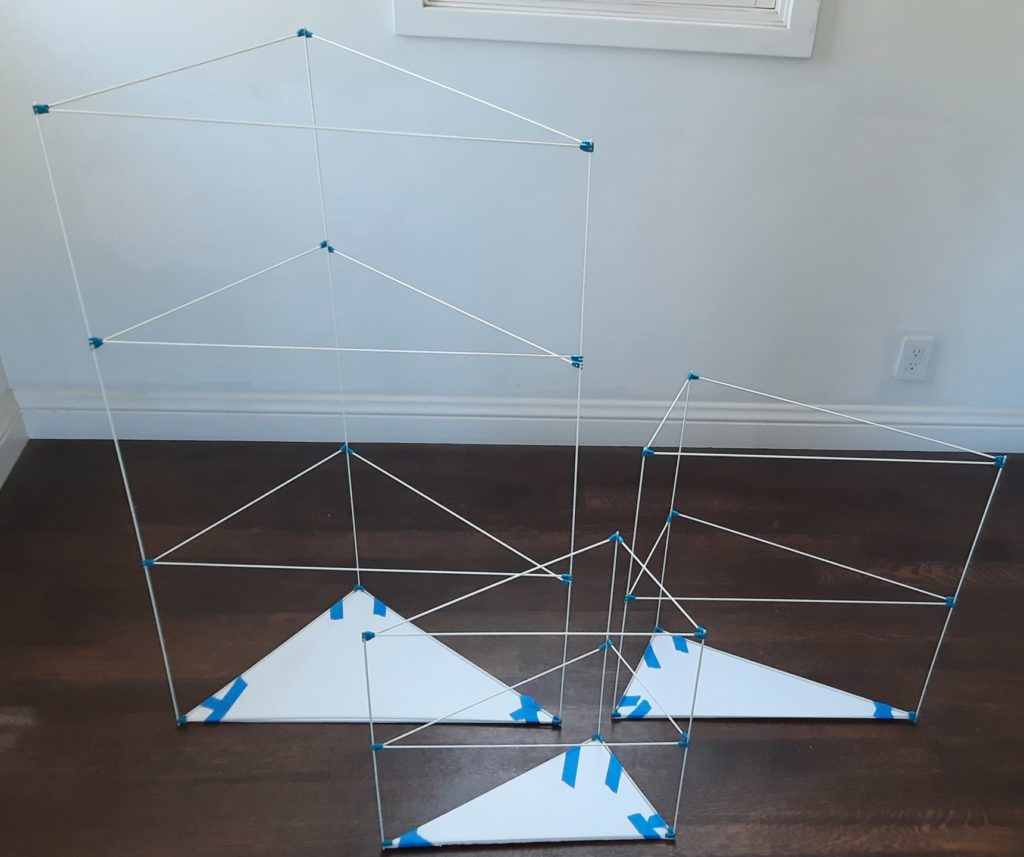
Every prism should have a triangle of edges at each end of the altitude, and at least one additional group of edges around its middle; the quantities above have been set so that the tallest prism D can have three internal sets of cross braces and B can have two. One set of cross braces at mid-height for prisms A and B seemed to be plenty. Note that the clips can interleave at the ends to produce triangles with coplanar rods, except for the two most acute angles (the sharpest angles of triangles A and B), where you will have to place them side by side. You can actually get a bit more stability on the taller prisms by staggering the interior cross braces slightly, rather than making each set coplanar. But on all of the prisms, the cross braces at the ends should be as close to coplanar as possible.

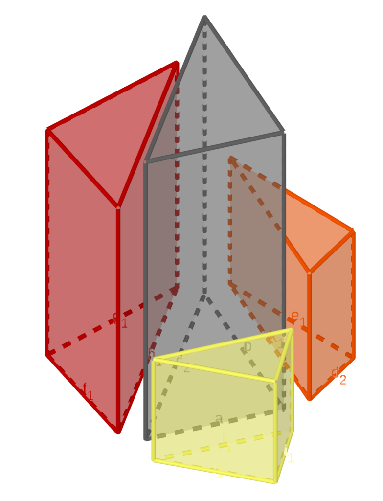
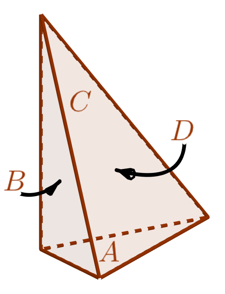
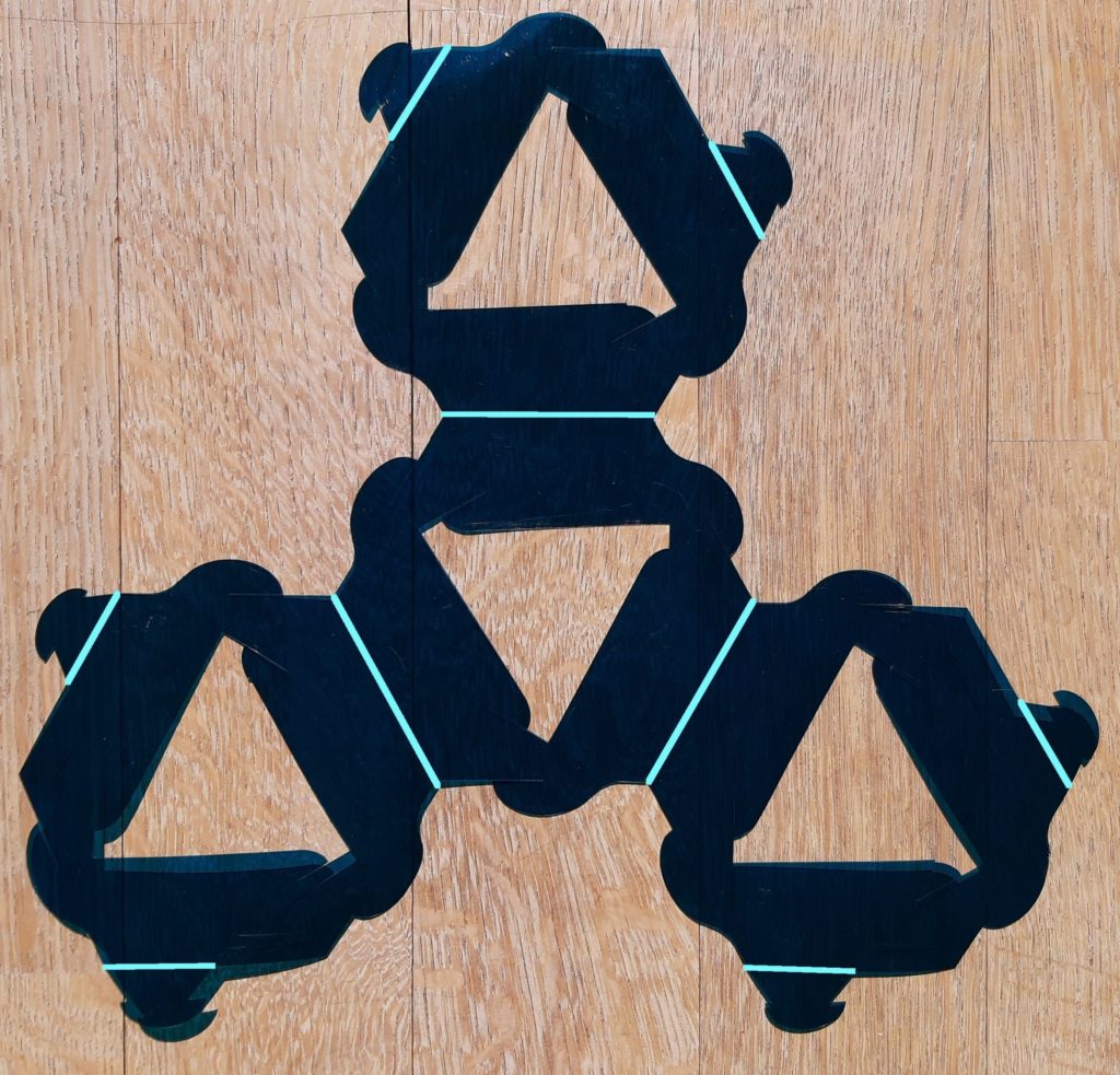
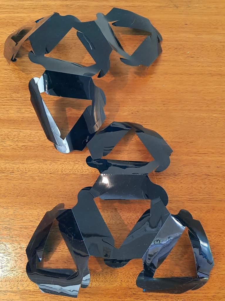
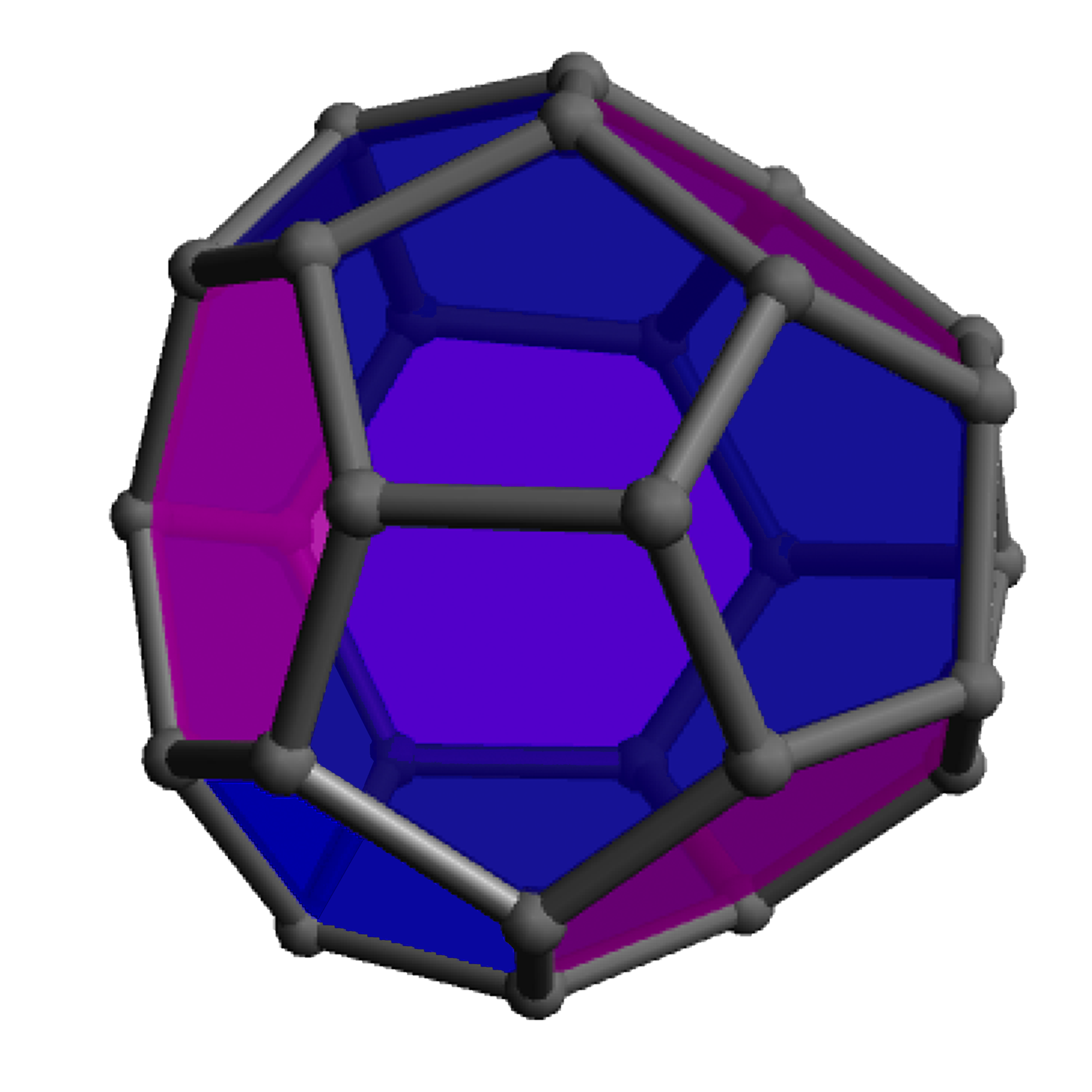
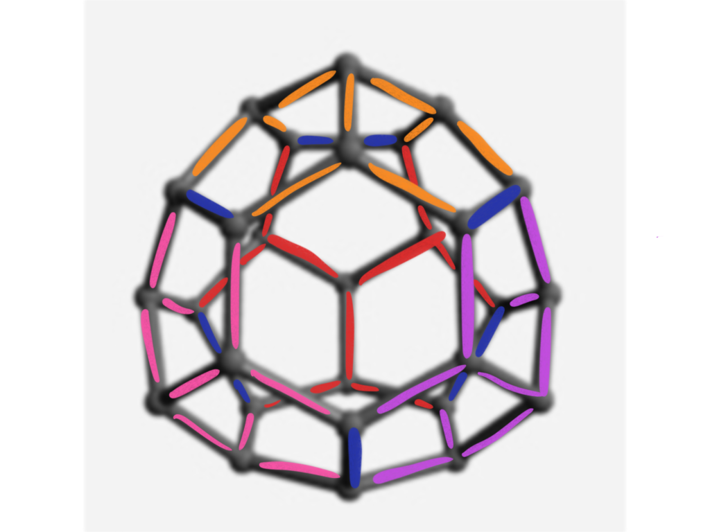
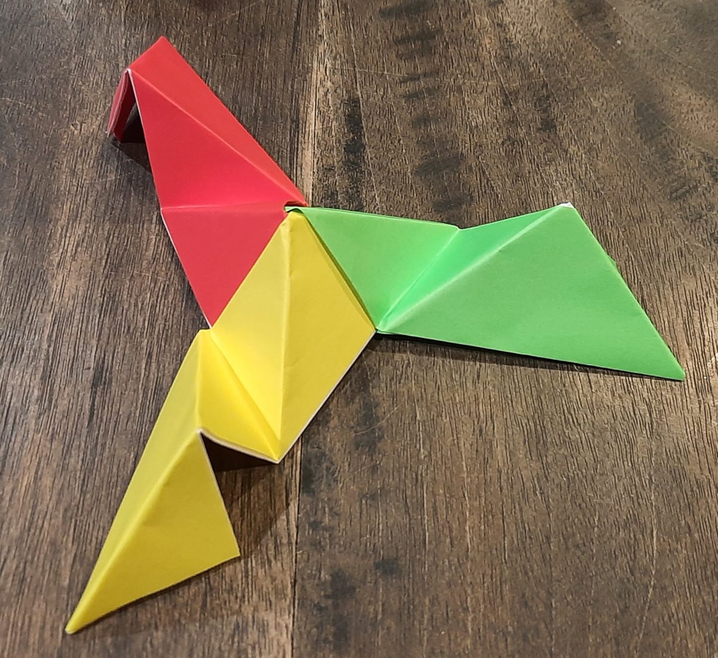
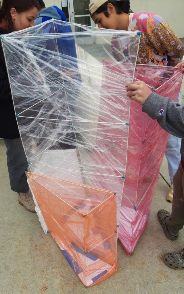
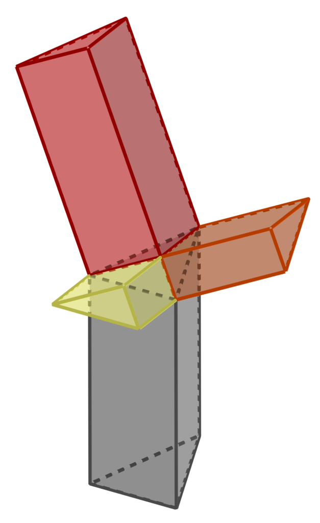
When you have made all the prism frameworks, attach the foam core bottoms to each prism with tape. For the finale, it matters a bit which end of each prism you attach the bottom to, and this is an aspect that was unfortunately not done correctly in the pictured build. The easiest way to get it right is to stand the D prism in the center, and then line up the A, B, and C prisms with their hypotenuses matching with the sides of prism D. Orient A, B, and C so that the legs of adjacent prisms match in length (see the diagram at left). Then attach the bottoms.

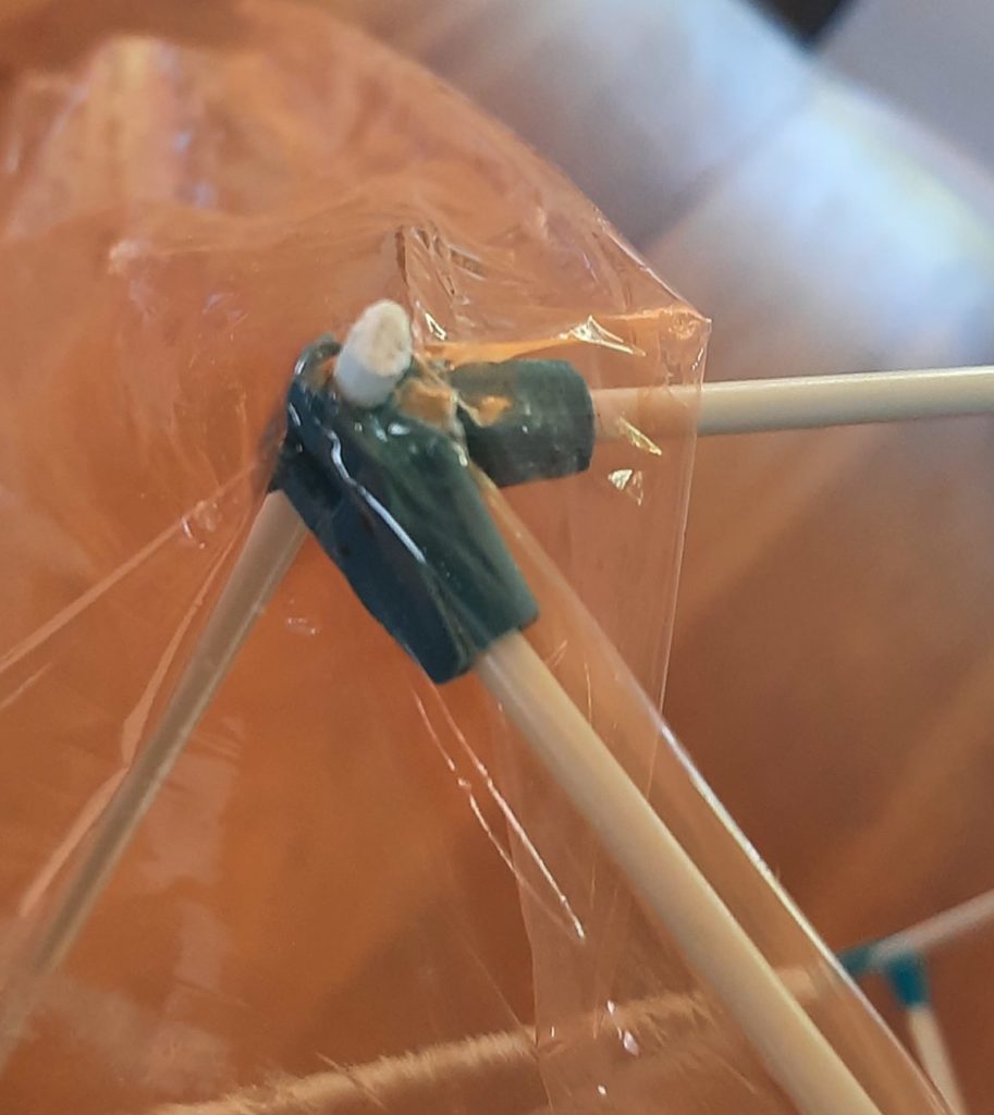
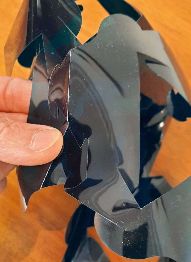
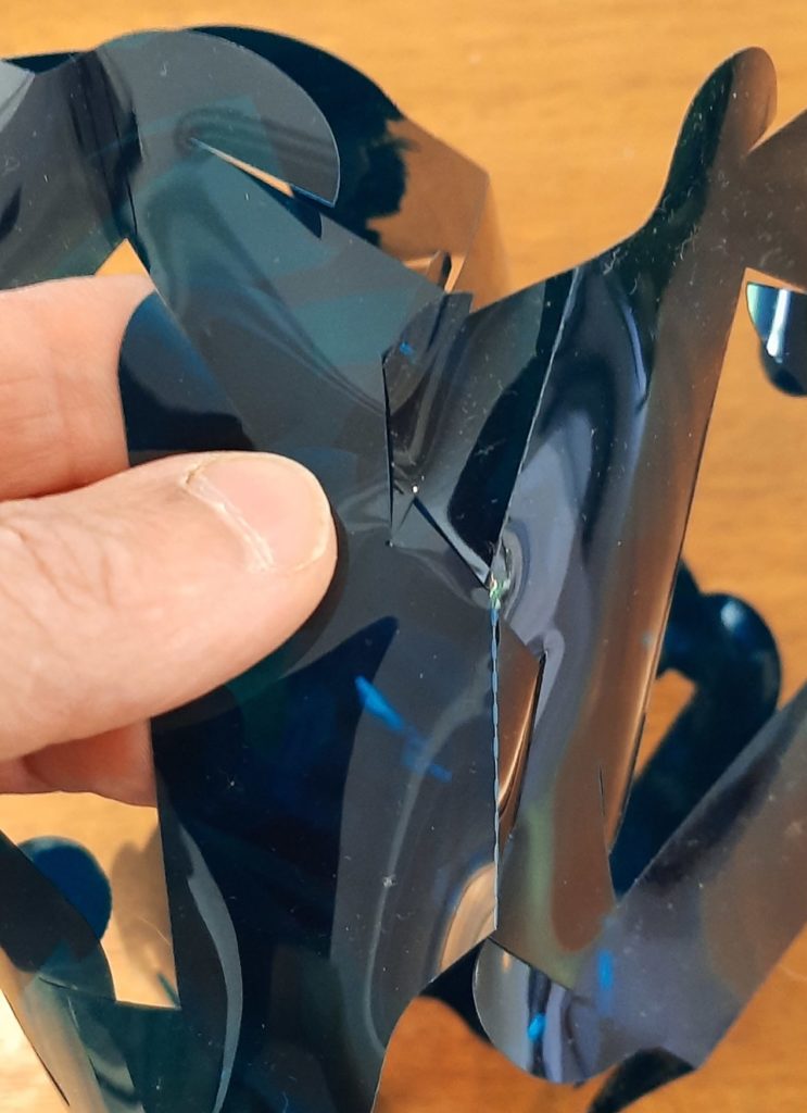
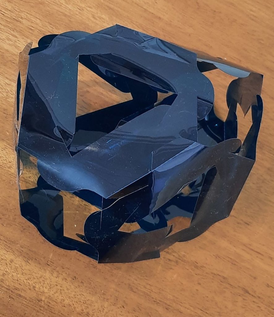
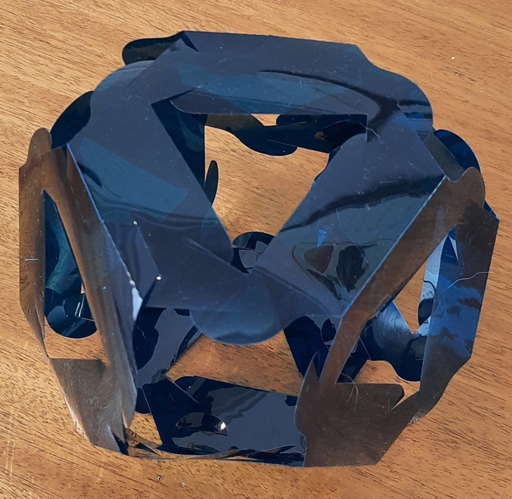
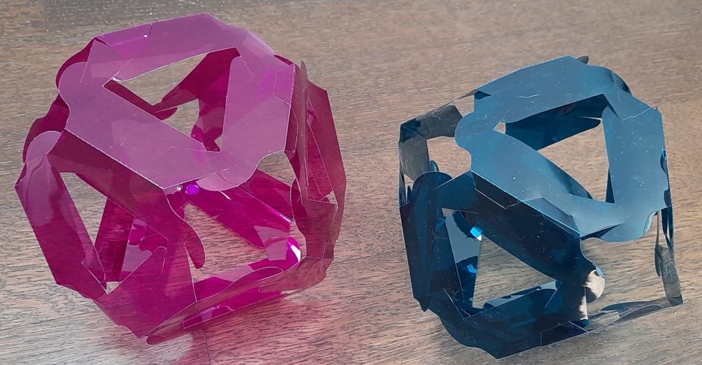
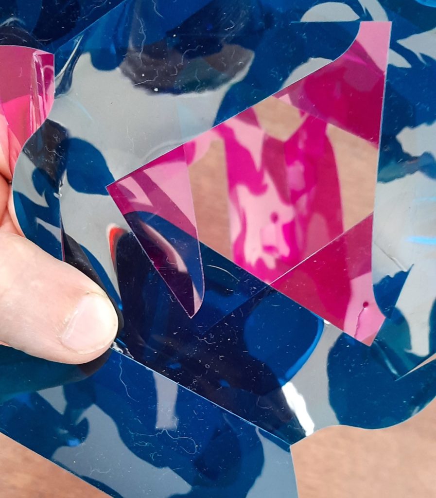
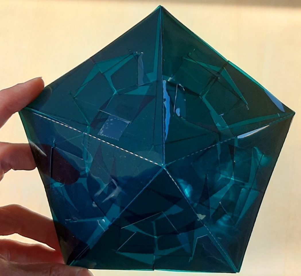
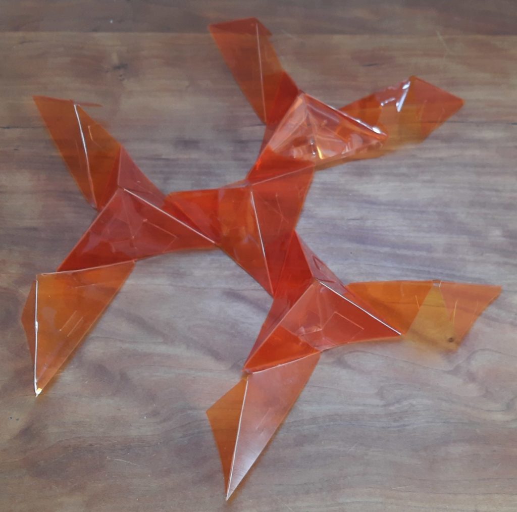
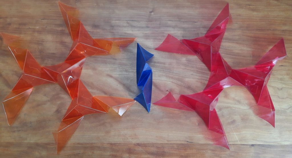
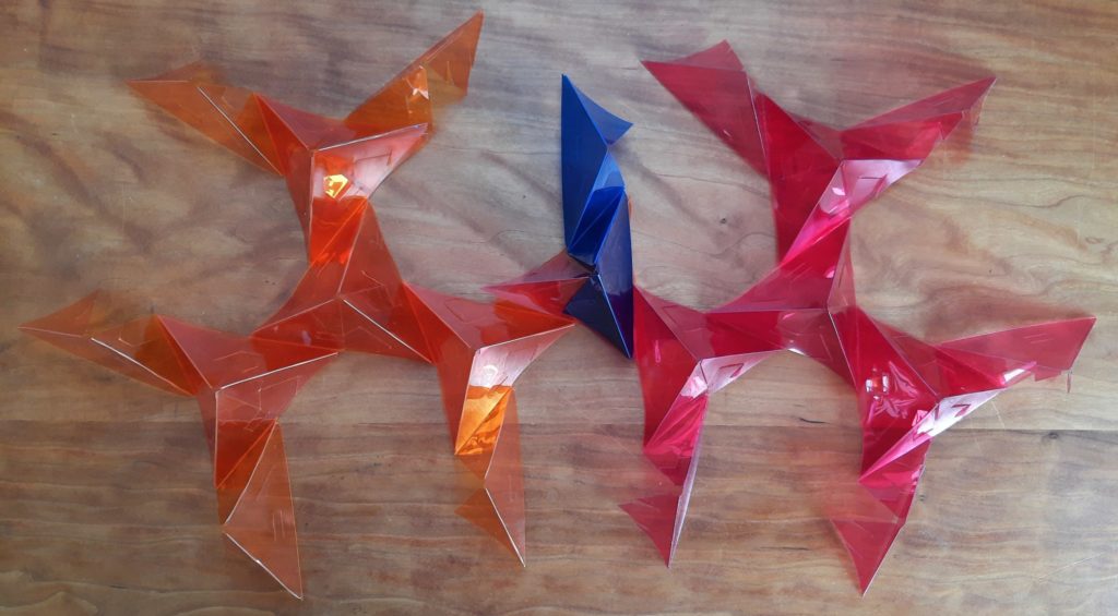
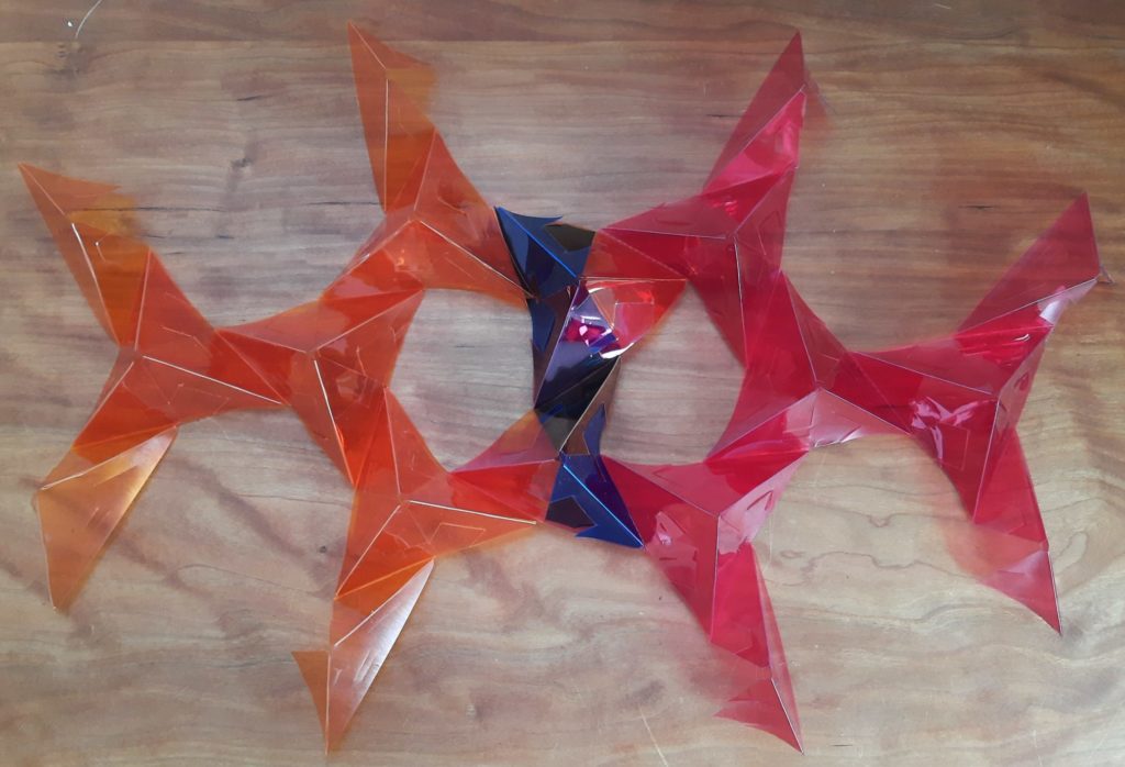
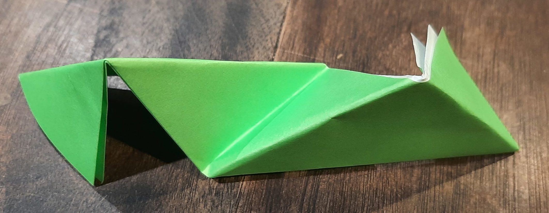
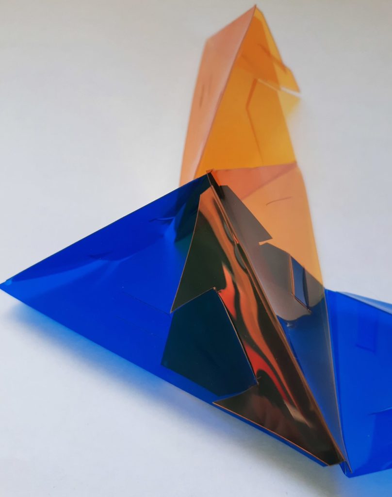
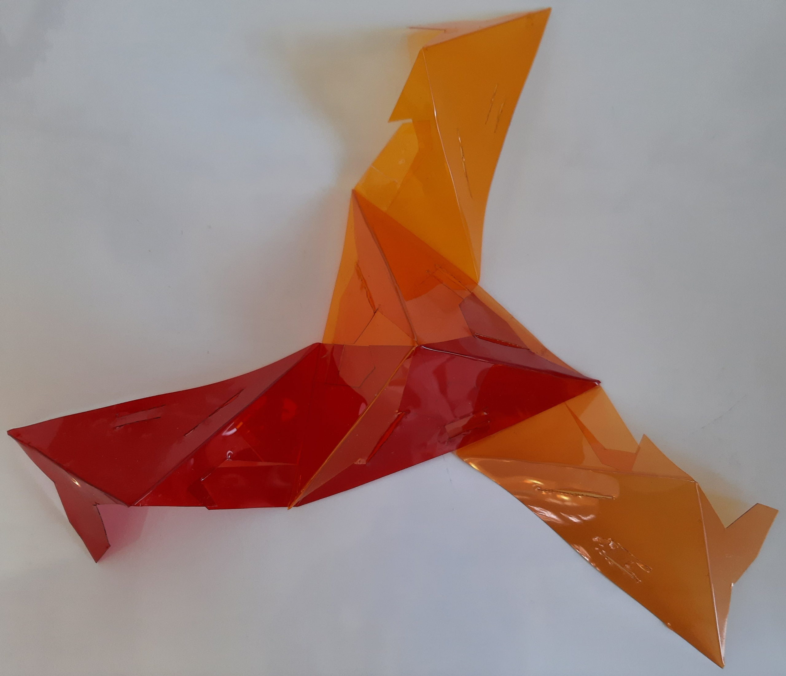
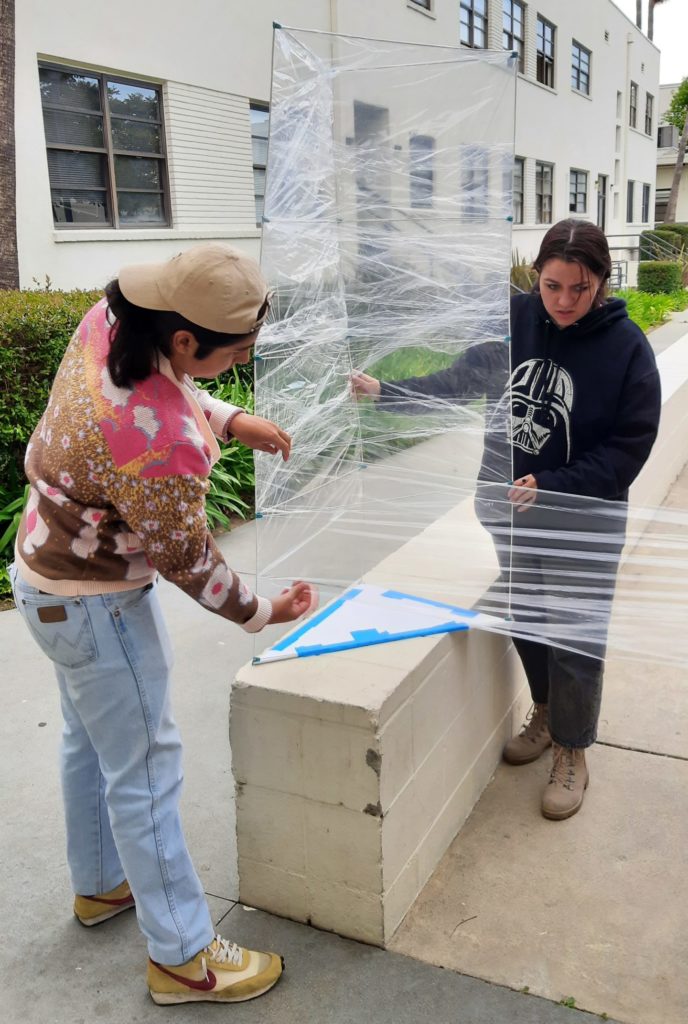
The last step in preparing for the finale is to add vertical sides to your prisms. This could be done with any sheet material (you could cut rectangles to size) but the quickest and easiest way, that also allows you to easily see what’s going on in the finale, is to wrap them with cling wrap. Industrial packaging wrap is readily available in a variety of colors, or you can use ordinary consumer food wrap (although you will likely need an entire roll). Begin the wrapping at the top by hooking the wrap onto one of the altitudes (see photo at right), and then leaving some extra wrap above the top crossbars, make one circuit of the triangular perimeter. Fold the extra down around the top crossbars, and then continue to wrap around the prism angling downward somewhat so that at least half the sheet overlaps with what’s already there at all times. Continue past the bottom panel of the prism, and then fold the excess underneath and secure with tape or by stretching and sticking the wrap to itself. The process and results are depicted below:

Once all of the prisms are wrapped, it’s time for the finale. Fill the three smaller prisms A, B, and C with loose, light filler material — we used water-soluble “packing peanuts.”

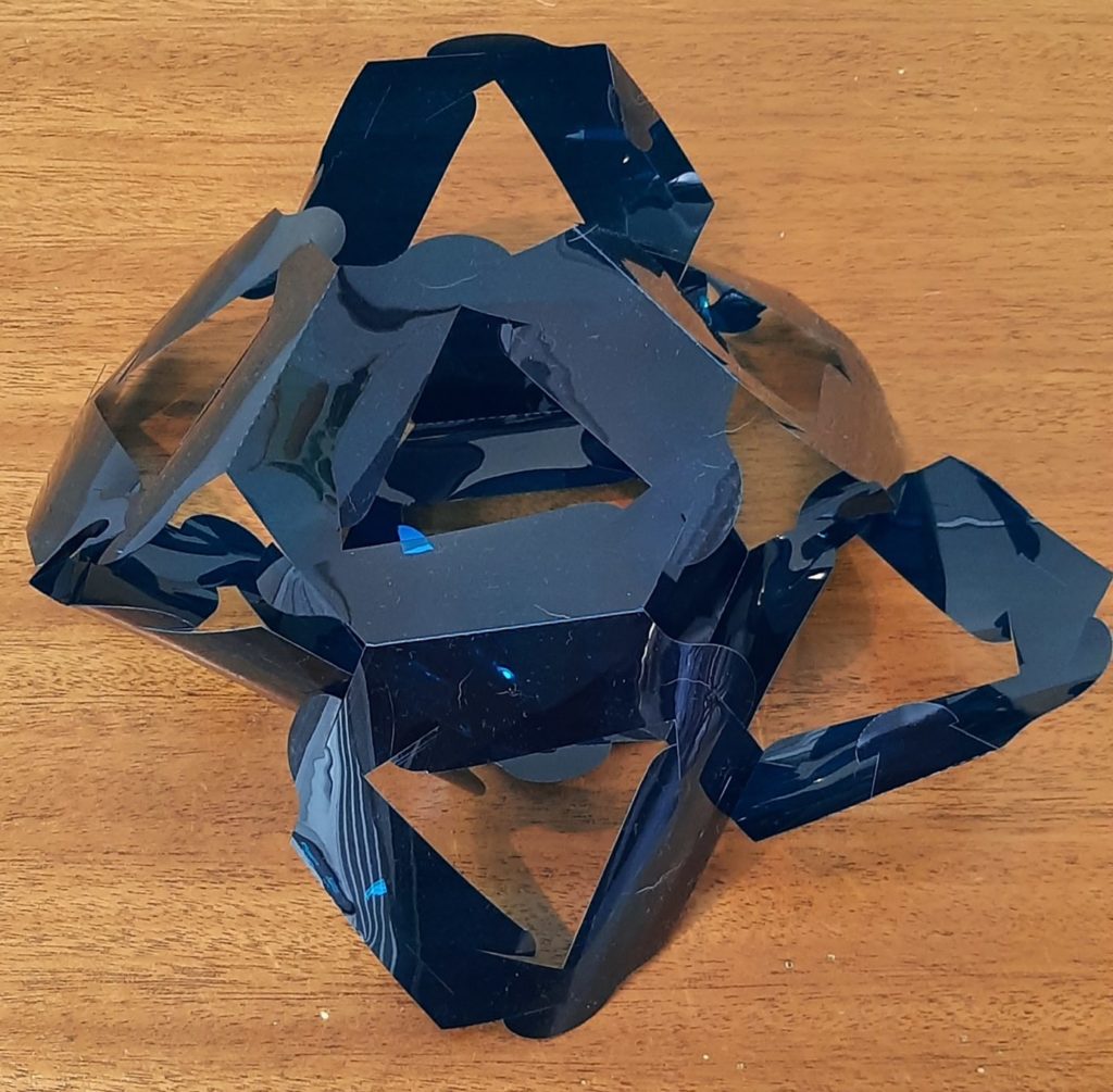
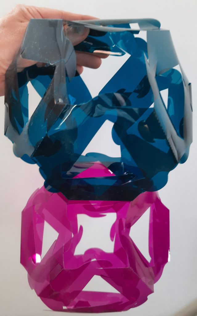
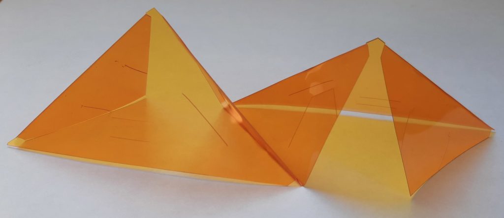
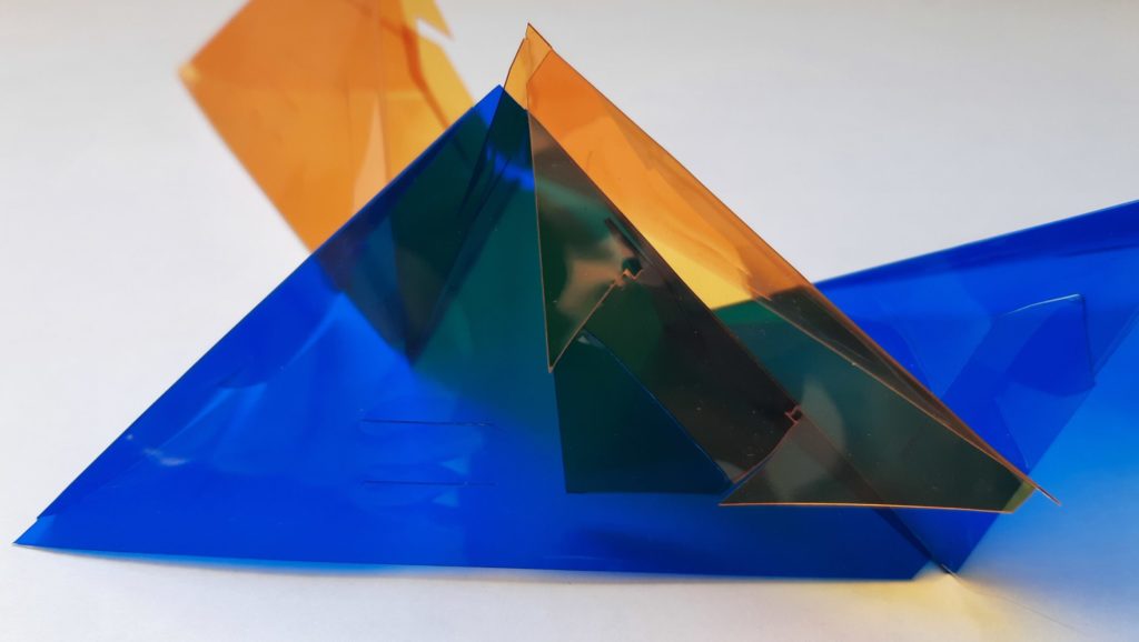
Ideally, if the bottoms are placed on the proper sides, you can now place loose temporary lids on top of prisms A, B, C, and invert them above prism D to create a space congruent to the right tetrahedron above prism D, showing the prisms of height equal to face area erected on all four faces of the tetrahedron. (See diagram at left for how that might look.) Then pull the temporary lids out and allow all of the filler material to tumble down into prism D.

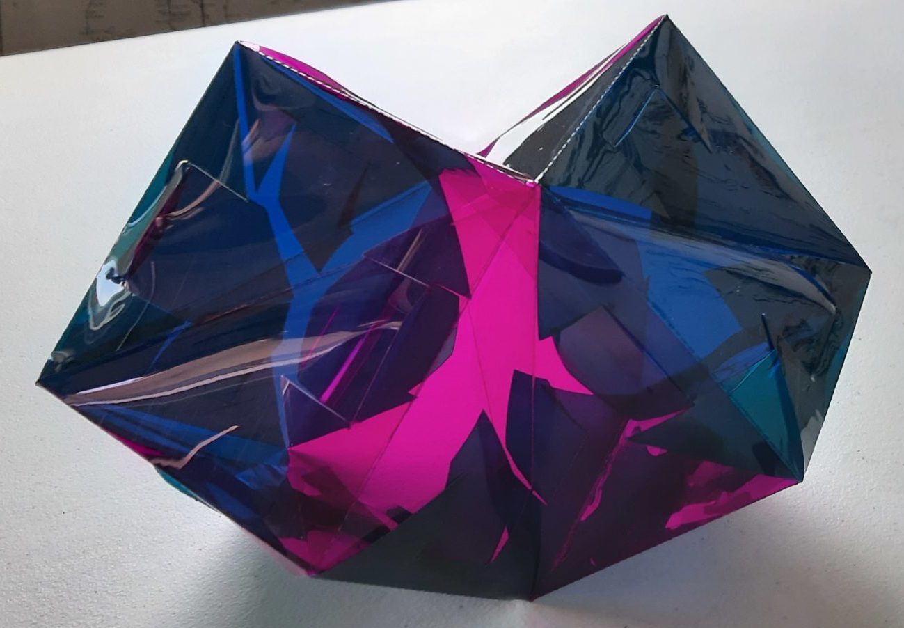
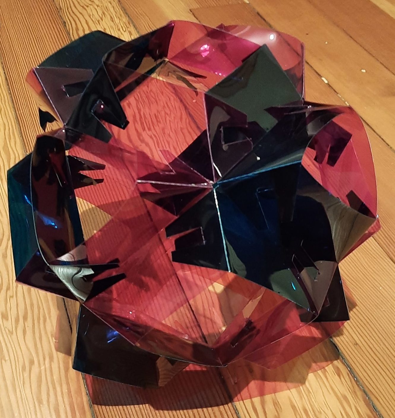
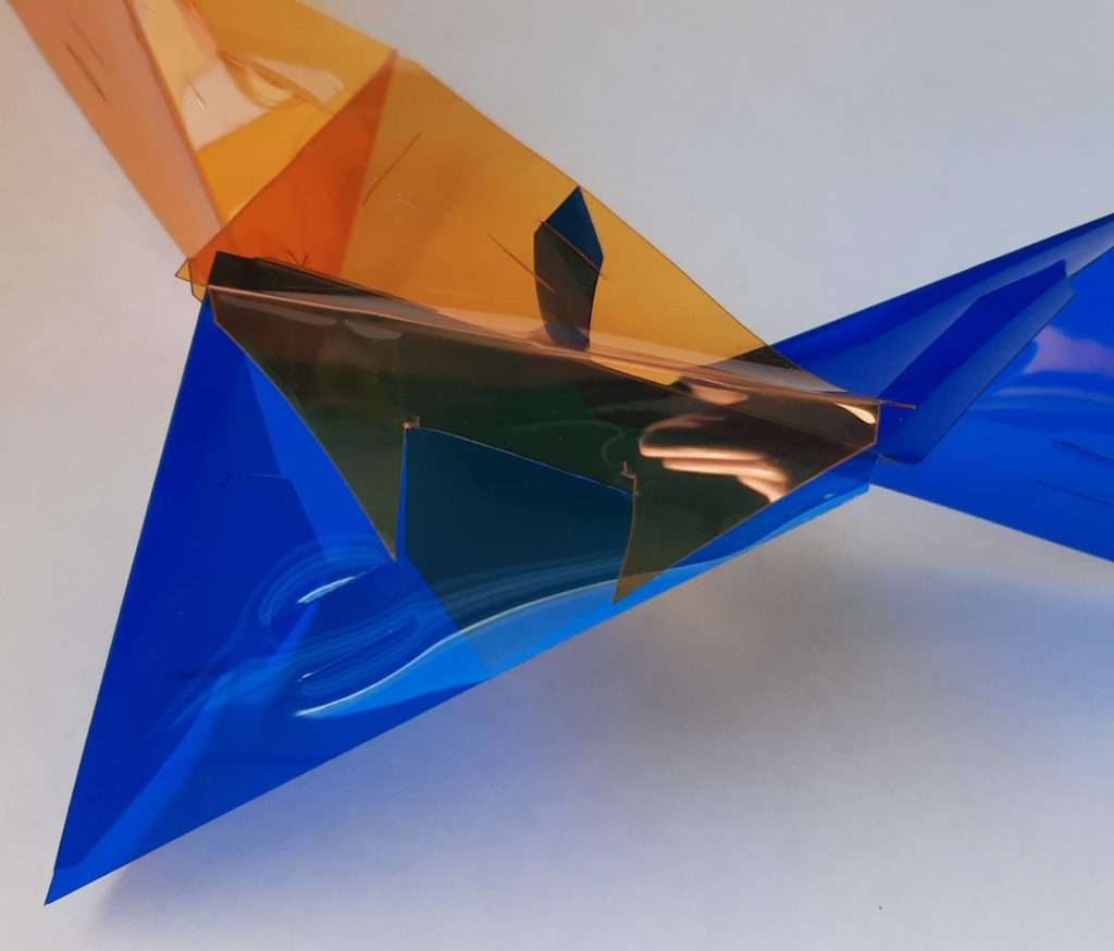
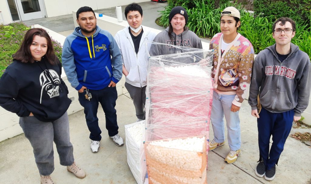
If that’s too complicated or the bottom panels were not on the correct ends, simply dump all of the contents of A, B, and C in turn into prism D (as depicted to right). Here’s what you get when you’re done:

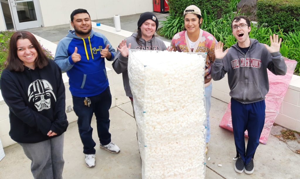
And voilà — the material exactly fills the largest prism D! Is this a coincidence? Seeing as how this is Studio Infinity, of course not. What are the volumes of these prisms? Well, letting A, B, C, and D also stand for the areas of the four faces, we have the height of prism A is also A, and so on through the height of prism D is D. And since the volume of a prism is the area of its base times its height, the volumes of the prisms are A2, B2, C2, and D2. And it turns out that for any right tetrahedron, A2 + B2 + C2 = D2 — this is the Three-D Pythagorean Theorem. So the big prism was guaranteed to fill up exactly!

(Many thanks to the students of LMU Math 490!)

20 Apr

Three-D Pythagorean Theorem

This recent post described a construction that demonstrated the “Three-D Pythagorean Theorem.” Here we dive a bit deeper into this bit of mathematics that may be less familiar than it deserves.

A right tetrahedron has, by definition, a vertex where three right angles meet (there can be only one). An example is shown in the diagram at right. Suppose that the areas of its faces are $A < B < C < D$. Then the Three-Dimensional Pythagorean Theorem (also known as de Gua’s Theorem) says that \[A^2 + B^2 + C^2 = D^2.\]

This is a generalization of the “usual” two-dimensional Pythagorean Theorem. How so? Here we say that one theorem “generalizes” another if it has the other theorem as a special case. How can we get the 2D theorem as a special case of the 3D? Unlike with most generalizations, it’s not particularly clear.

Because the area of square BEFD is twice that of ABCD, the diagonal BD is √2 times the side length AB.

In fact, I was only able to derive the usual PT from the 3D one if I also presumed the special case case of the usual PT that the diagonal of a square is √2 times its side — but that case is quite simple to prove on its own, by considering a 2-by-2 grid of squares and four of the diagonals of squares in that grid that themselves form a square (you can see essentially the full proof to the left).

Now, assuming the 3D Pythagorean Theorem and the fact that the diagonal of a square is √2 times its side, we derive the usual Pythagorean Theorem as follows: Let $a$ and $b$ be arbitrary lengths, and consider the right tetrahedron with legs (edges meeting at the right-angle vertex) of lengths $a$, $b$, and $b$.

Then the edges of the base (the face that does not include the right-angle vertex) of this right tetrahedron are $c$, $c$, and $\sqrt{2}b$, where $c$ is the hypotenuse of a right triangle with sides $a$ and $b$ (see the diagram at right). The areas of the other three faces are $ab/2$, $ab/2$, and $b^2/2$. Hence, by the 3D PT, the area of the base is $b^2(2a^2 + b^2)/4$, and so the height $h$ of the base (from the vertex between the two sides of length $c$) is $\sqrt{a^2 +b^2/2}$. But the altitude of an isosceles triangle bisects the third side, so $c$ is also the hypotenuse of a right triangle with legs $b/\sqrt2$ and $\sqrt{a^2+b^2/2}$.

Iterating this construction, we see that $c$ must also be the hypotenuse of a right triangle with legs $b/2$ and $\sqrt{a^2+3b^2/4}$. Iterating further, $c$ must also be the hypotenuse of a right triangle with legs $b/4$ and $\sqrt{a^2+15b^2/16}$, and further in general $c$ is the hypotenuse of a right triangle with legs $b/2^n$ and $\sqrt{a^2 + b^2(2^{2n}-1)/2^{2n}}$. Taking the limit as $n$ grows without bound, $b/2^n$ approaches zero and $(2^{2n}-1)/2^{2n}$ approaches one, and we see that $c$ must equal $\sqrt{a^2+b^2}$, as desired.

Of course, one would never really prove the usual Pythagorean Theorem in this way; the above merely serves to justify calling the 3D PT a “generalization” of the usual one, in that we can recover the usual one from it.

All this begs the question, how do we prove the Three-D Pythagorean Theorem itself? The simplest way is to generalize the following atypical “proof” of the usual Pythagorean Theorem:

Place a right triangle with legs $a$ and $b$ on a coordinate plane so that the vertex of its right angle is at the origin and the legs extend along the $x$ and $y$ axes, respectively. Then by the two-intercept form of a line, the equation of the line containing the hypotenuse is $x/a + y/b = 1$. Also, the line through the origin given by $y=ax/b$ is perpendicular to the hypotenuse (see the diagram to the left, with the hypotenuse in blue). These two lines intersect at the point $(ab^2/(b^2+a^2), a^2b/(b^2+a^2))$. The line segment from the origin to this point (dark green in the diagram) has length $ab/\sqrt{a^2+b^2}$. But this line segment is also an altitude of the right triangle with respect to the hypotenuse as base. Since the area of the rectangle is $ab/2$, by dividing we get that the hypotenuse of the right triangle must be $\sqrt{a^2+b^2}$.

I put “proof” in quotes because it’s circular — I actually used the Pythagorean Theorem to get the length of the altitude segment. However, if we do the same proof in three dimensions, we still only need the ordinary Pythagorean Theorem to get the length of the corresponding segment, and so we get a bona fide proof of the 3D Pythagorean Theorem (using the usual PT, which is OK because as mentioned, we would not actually use the 3D PT to prove the usual 2D PT — there are plenty of independent proofs). That goes like so:

Place a right tetrahedron with legs $a$, $b$, and $c$ in a coordinate system so that its right-angled vertex is at the origin and the legs extend along the $x$, $y$, and $z$ axes, respectively. Then by the three-intercept form of a plane, the equation of the plane containing the base of the right tetrahedron is $x/a + y/b + z/c = 1$. (See the diagram to the right.) Also, the line through the origin given in parametric from with parameter $t$ by $(x,y,z) = (bct, act, abt)$ is perpendicular to the base (you can check this by taking the dot product of $(bc, ac, ab)$ with the two vectors $(a,-b,0)$ and $(0,b, -c)$ which both clearly lie in the plane of the base). This line intersects the plane at the point \[\left(\frac{a(bc)^2}{(bc)^2+(ac)^2+(ab)^2},\frac{b(ac)^2}{(bc)^2+(ac)^2+(ab)^2},\frac{c(ab)^2}{(bc)^2+(ac)^2+(ab)^2}\right).\] The line segment from the origin to this point has length $abc/\sqrt{(bc)^2+(ac)^2+(ab)^2}$ (that’s where I’m using the regular PT). But this line segment (dashed green in the diagram) is also an altitude of the tetrahedron to the base. Since the volume of the tetrahedron is $abc/6$, the area of the base must be $\frac12\sqrt{(bc)^2+(ac)^2+(ab)^2}$. So indeed the square of the area of the base is $(bc/2)^2 + (ac/2)^2 + (ab/2)^2$, which is the sum of the squares of the areas of the other three sides as desired.

In case you’re wondering, the Pythagorean Theorem does generalize in this way to $n$ dimensions: the square of the $(n-1)$-hypervolume of the base of a right $n$-simplex is the sum of the squares of $(n-1)$-hypervolumes of the other faces, and the exact same proof as just given, except with more variables and an $n!$ in place of “6,” works.

12 Apr

New Call for Problems

Hey, I have recently become the Problem Warden for the Prison Math Project (PMP). That means I’m the editor of The Prisoner’s Dilemma, the quarterly problem section of the PMP newsletter. So I’d love it if you have intersting problems or mathematical puzzles to submit to the column. Of course, you will be credited online and in the newsletter for any problems you submit.

I also welcome solutions to the existing problems from anyone. Problems range in difficulty from high-school contest level up to roughly the easiest end of Putnam competition problems. So to submit problems or solutions, please email me at dilemma “at” pmathp “dot” org. Looking forward to your ideas!

09 Apr

Tessellating Truncated Octahedra

With all of the recent activity at Studio Infinity on geometric units that can be automatically cut and scored, it was natural for the S∞ G4G14 giveaway to be the 14-sided Truncated Octahedron, which tessellates to fill space. The additional challenge here as compared to some of the earlier interlocking structures was to ensure that the resulting polyhedral units would be able to connect arbitrarily face-to-face, so that it’s possible to explore the three-dimensional structures you can build with multiple truncated octahedra.

This was accomplished by two measures. First, by leaving the square faces empty (fortunately the truncated octahedron is still rigid with its square faces deleted) and putting connection tabs similar to ITSPHUN units on the corresponding edges. That step allows any square face to connect to any other square face, in any of the four possible orientations.

Second, I cut out a triangle (not a hexagon!) from the center of each hexagonal face, and added similar connection tabs to those. That allows any hexagonal face to connect with any other hexagonal face, but only in the three orientations that allow the space-filling tessellation to continue.

These ideas result in the following SVG template:

The black lines are cuts and the magenta dashed lines are scores (all for mountain folds). If you are cutting directly from this SVG, you can also cut just the dashes of the magenta lines on very low pressure/high speed to create scores that fold well.There are two units because it takes two to create a single truncated octahedron, and to illustrate how they interleave for cutting, leaving very little unused material. (The outermost protruding tabs are for connecting these two pieces into one polyhedral unit.) In case it’s helpful, here are a PDF and the DXF design file for this unit.

See the previous post for full assembly instructions. I’ll leave you with an image of the smallest loop one can make, with six completed units.

If you build an interesting structure with these units, please post a picture in the comments!

09 Apr

Assembling a TTO

These are the assembly instructions for the Tessellating Truncated Octahedra; you’ll find background and the cut files for them on them in the following post.

Materials
Two TTO pieces per unit you wish to build

The first order of business is to fully cut and punch out two of the pieces from the cut templates in the following post, including removing the triangular inserts in the four hexagonal faces, and separating all of the tabs and slots. That will produce a piece that looks like the following picture (with the score lines in the template highlighted by light blue lines, as otherwise they are difficult to see in the photograph):

Now make a mountain fold on each of the score lines, producing something that looks like this:

Repeat with another piece. Two of them will interlock to produce a single truncated octahedron unit. The picture on the left below shows them overlapped in roughly the relationship they will have when connected; the picture on the right shows two of the edges lined up ready to be connected.

To connect this edge, start inserting the long flap of one of the tabs on that edge into the slit opposite it on the other piece, then pull that tab all the way in, then repeat with the other tab along that edge (on the piece that has the slit in the first part of the connection, going into a slit on the piece that had the tab). This process is shown in the following sequence of three photos:

Now work your way around the unit, connecting six edges in all. The left photo below shows me working on the second edge, and the right photo shows the state with three edges connected.

When you’ve done all six edges, you’ve completed your first truncated octahedron unit, which looks like this:

But the distinctive thing about these truncated octahedra units is that they can connect arbitrarily face to face in their tessellation of space. Connecting square faces (which are empty in each individual unit) is relatively straightforward: just line up their edges however you’d like and engage the four pairs of corresponding (but opposite-pointing) edges. Connecting the hexagonal faces is just slightly trickier, because they line up in the tessellation in only three (not six) ways. (The other three ways would force two square edges to be adjacent; but as each TO unit does not have any adjacent square edges, that can’t happen in the tessellation.) So you have to line up two units so that the tabs in their triangular cutouts will engage, like so:

Then line the corresponding faces up with each other and engage the three tabs around the triangular cutouts. (You may have to bend the tabs back pretty far to get them past each other to engage, so hopefully you’ve cut your pieces out of a sufficiently flexible material, like this plastic — Roscolene lighting gel, to be exact — paper and cardstock will also work fine if you’re OK with opaque units.) Here’s me having just connected one pair of tabs around a triangular opening:

Once all three pairs of tabs are engaged, you’ll find the connection to be quite robust:

Enjoy assembling and connecting your Tessellating Truncated Octahedra! What kinds of loops, bridges, and shapes can you build?

09 Apr

More Non-origami Modules

Another aspect of the PCMI session on Illustrating Math was a series of exploratory, hands-on workshops. One of them focused, in part, on the design of modules like the one for the truncated triakis tetrahedron, but based on other existing modular origami units.

It’s more or less possible to transpose any modular origami unit to a cut-and-score single-sheet module with tabs and slits, as the following table of designs from the workshop shows:

Modular origami unitSVG of cut-and-score designDXF of designSample construction
SonobeSonobe.dxf
PenultimatePenultimate.dxf
135° UnitWS135.dxf
ReptileReptile.dxf

A key difference that emerged from these workshop examples as compared to the PHiZZ units is that this plastic sheet material produced beautiful results on these geometrically exact units, whereas it did not distribute the slight geometric imprecisions inherent in PHiZZ unit constructions nearly as well as paper units do. (Many of the modular plastic PHiZZ constructions end up looking slightly lopsided, whereas the models from the workshop were all extremely crisp.) This distinction definitely plays into future material selection for geometric constructions.

09 Apr

Truncated Triakis Tetrahedron

Materials
42 modular units cut out and folded (see Modular Origami, without the origami)
(preferably 9 each of four colors and 6 of another)

For the actual building event mentioned in the previous post (linked above), participants could choose from a variety of target polyhedra. The origami inspiration was the PHiZZ unit, which stands for Pentgons Hexagons in Zig Zag, so the ideal targets consist of just pentagons and hexagons. With Euler’s formula for polyhedra and a little calculation you can determine that such a shape must have exactly twelve pentagons and almost any number of hexagons; the page for the event includes a table of candidates.

I chose the Truncated Triakis Tetrahedron as my target: (not only because of the alliteration, it’s a nice size and has pleasing symmetry that breaks the building down into four simple, identical sub-assemblies)

To assemble this, I worked from a diagram of the edges, graciously colorized by Elliot Kienzle:

I found it easiest to start by making each of the lighter-colored sections. They’re all the same, made of nine pieces each. You make one three-way connection all the same color (as shown in the previous post), and then turn each of the three opposite ends of each of these pieces into a three-way connection, like so:

Repeat with the other three colors.

When you have your four sub-assemblies, you can connect two neighboring loose ends of one color with corresponding loose ends of another color at the two ends of a new unit of the darker color. Here are the components laid out schematically to show how they go together:

And here they are overlapped in the actual way the first trio of connections will be made:

And here they are once both ends of the blue unit have been fully connected:

This process of connecting sub-assemblies with one additional unit happens in six places, shown by the blue edges in Elliot’s diagram above. (These six edges are actually the remnants of the six original edges of the tetrahedron that the truncated triakis tetrahedron is based on.) Once you’ve made all those links, everything hangs together like so:

(Note that this image is shown from the same perspective as Elliott’s diagram above, used as the construction guide.)

Participants took this basic concept in a variety of directions, and here’s a mini-gallery of some of the results:

Emily Z
Katherine Booth (75 edges!)
Kate Stange
Rémi Coulon
Gabriel Dorfsman-Hopkins
As a final bonus, the units are flexible enough so that you can break the pentagon/hexagon only rule: this shape is made by connecting just two of the truncated triakis tetrahedron sub-assemblies to each other in all three possible places, and it contains three quadrilaterals and six pentagons.
08 Apr

Modular Origami, without the origami

In many ways, modular origami is ideally suited for the type of exploratory mathematical play that S∞ is dedicated to: it’s easy to get started, very tactile, and offers nearly endless opportunities for creating interesting and beautiful objects. For example, here’s a PHiZZ unit torus that resulted from a workshop I led at The Brearley School (photo courtesy of Maggie Maluf).

But the backstory to that wonderful construction is that folding the hundreds of units required to assemble the torus took so much time that by the end of the scheduled workshop, only about a quarter of the torus was connected, and piles of PHiZZ units were strewn around the room. (Unfortunately – but unsurprisingly – I don’t seem to have a picture of this scene.) The torus was only salvaged through the valiant efforts of the school’s math club and its coach over many lunchtimes.

This anecdote highlights one weakness of modular origami – if you’re interested in building something big, folding all of the individual units necessary can be tedious and time-consuming. Hence, I’ve often wondered why there isn’t a construction toy that consists of reusable bendable pieces modeled after one of the popular modular origami units.

Two developments moved that concept from contemplation to a recent Studio Infinity project: the first is the constant improvement in hobbyist-level automated cutting machines, some of which now have dual tool slots, potentially ideal for cutting and scoring. (I use a Silhouette Cameo 4 Pro, partly because its two-foot width accommodates some materials available in bulk rolls, but there are numerous capable machines on the market – this shouldn’t be construed as an endorsement of that particular machine.)

The second was the need and opportunity for a group mathematical event for the summer 2021 Illustrating Math program at the Park City Math Institute. Since the event was virtual, it had to be easy to send any necessary supplies to the participants. Pre-cut and scored flat components seemed ideal.

I decided to stick with something modeled on the familiar PHiZZ unit for this first foray into modular origami-less construction. It also has a very simple geometry – here’s an example of a single unit:

A square sheet of paper is accordion-folded in quarters, and the resulting strip is pleated in isosceles right triangles. They usually connect in threes, as in this photo:

The idea was to create a cut/score template that would produce a piece with the same essential geometry, that could be produced in bulk on an automated cutting machine from a roll of material. In fact, choosing the material posed the first challenge. After much experimentation, I settled on the stiffest theatrical lighting gel I could find, namely Roscolene. This comes in two-foot wide rolls in a selection of striking translucent colors, and holds a crease very well, while cutting readily. Brittleness is its major drawback — I’d rather use tear-resistant mylar, but have so far had difficulty locating rolls of colored mylar sheet.

The next challenge was to figure out the connections. The paper PHiZZ units work because the initial accordion fold creates pockets that one end of the adjacent unit slides into. Since these units were to be cut from a single layer in the final 4:1 aspect ratio, no pockets were possible. (One could cut and pre-score 2:1 rectangles that fold in half to preserve the pocket mechanism, at the expense of using twice as much plastic and losing some of the translucency in doubling the layers.) Instead, venerable tab-and-slit designs can replace the pockets as a connection mechanism. Multiple prototypes led to the following design used to produce thousands of units sent to program participants:

The pink line is a score for a mountain fold, the green lines are scores for valley folds, and the red and black lines are cuts. (Of course, you can reverse mountain and valley as long as you do all of the pieces the same way, in which case your units will come out mirror-imaged from the ones below, although matching the paper ones above.) The small “divots” in the rectangle’s perimeter help align the folds along the scores. The above image is an SVG that can be used directly for cutting with the software for many machines, but if it’s helpful, here’s a PDF of the design (you can print on paper and cut by hand — but that’s even more tedious than origami), and the DXF file used to draft it.

When you have a piece all cut out and all the tabs and slits separated and folded as above, it looks like so:

To connect two units, start as shown in the left picture below: insert the large tab from the end of one unit (the orange one here) from above into the corresponding slit about a third of the way along another unit below (the blue one in the picture).

Then reach underneath the top unit and feed the thin tab of the bottom unit up through the lower slit in the top unit, as shown in the right-hand picture above. Then bend it around and back down through the top slit as shown in the picture on the left below:

Then push this tab all the way in — it’s like a belt buckle — to finish off the connection. It should look like the picture on the right above.

To wrap up this post, here’s three units assembled like the paper triad above.

The next post will cover building full polyhedra from these units.