05 Apr

Boxtahedral Trusses

Ok, all of the ingredients were in place to plan a large-scale construction for the Golden Gate STEM Fair: cubical units that can attach at edges and the theory linking them to the oct-tet lattice. I just needed to put it all together into a plan for something interesting and substantial that could be built out of lots of 6″ cubes (but not too many). Since height is a key factor in drawing attention, a nice round figure of 5 meters seemed like a good goal height for the structure. But what to build?

(Note that this post is intermediate between the MakeStream and the MathStream; there’s not much theoretical going on here, but neither is anything physical getting built. Instead, this post is about planning and modeling, so I will leave it in MakeStream and tag it as “virtual.”)

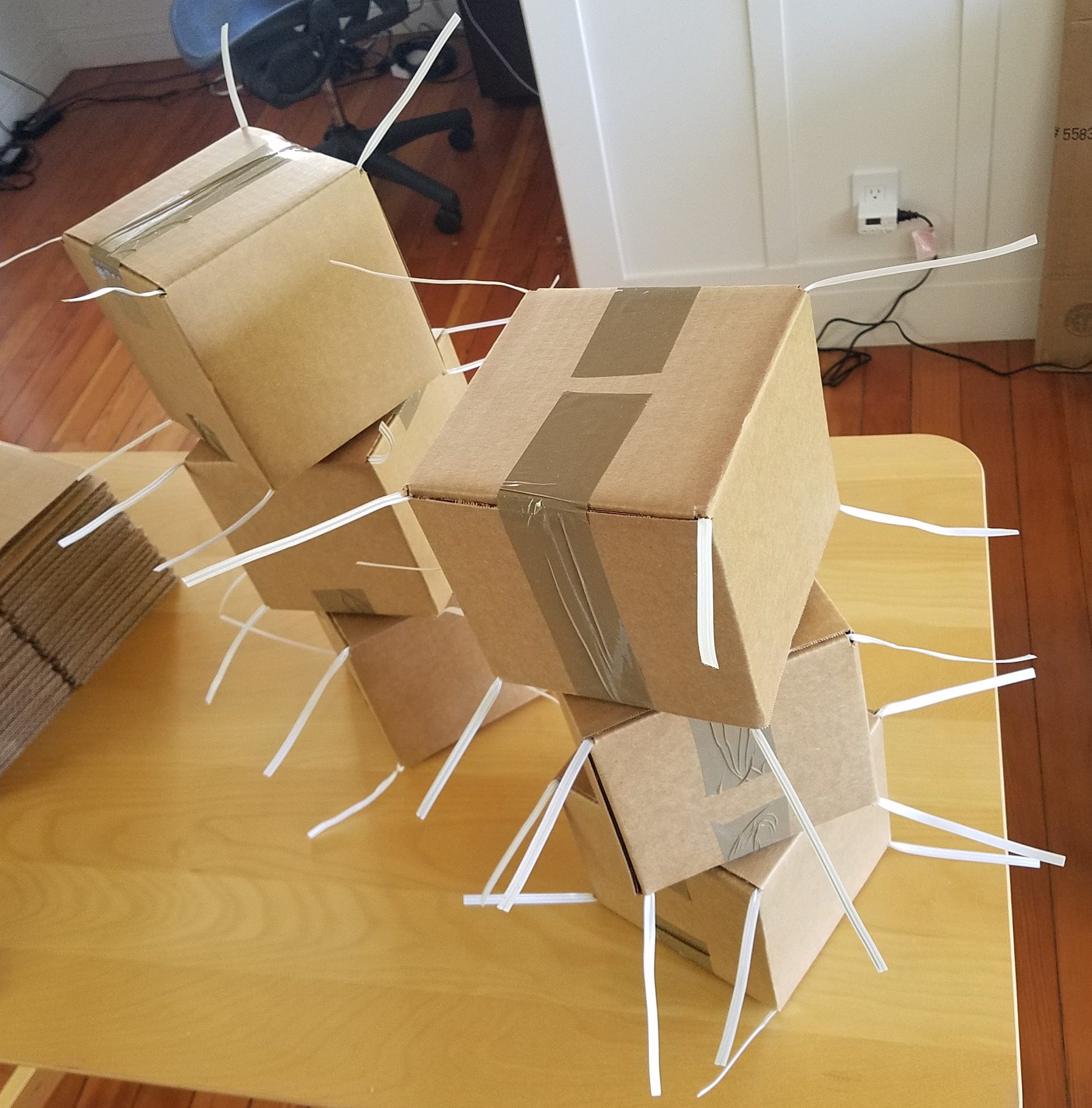
A first natural structure to build in the oct-tet lattice is an oct-tet truss, comprised of a row of octahedra with the tetrahdedra that bind them together.
Notice that there end up being four parallel chains of struts that extend straight along the truss, at the top, bottom, and both sides. That observation means that oct-tet trusses (perhaps unsurprisingly) proceed along the strut directions of the oct-tet lattice. In other words, we should be able to connect the trusses up at the same angles (60°, 90°, 120°, etc.) as the struts of the oct-tet lattice.

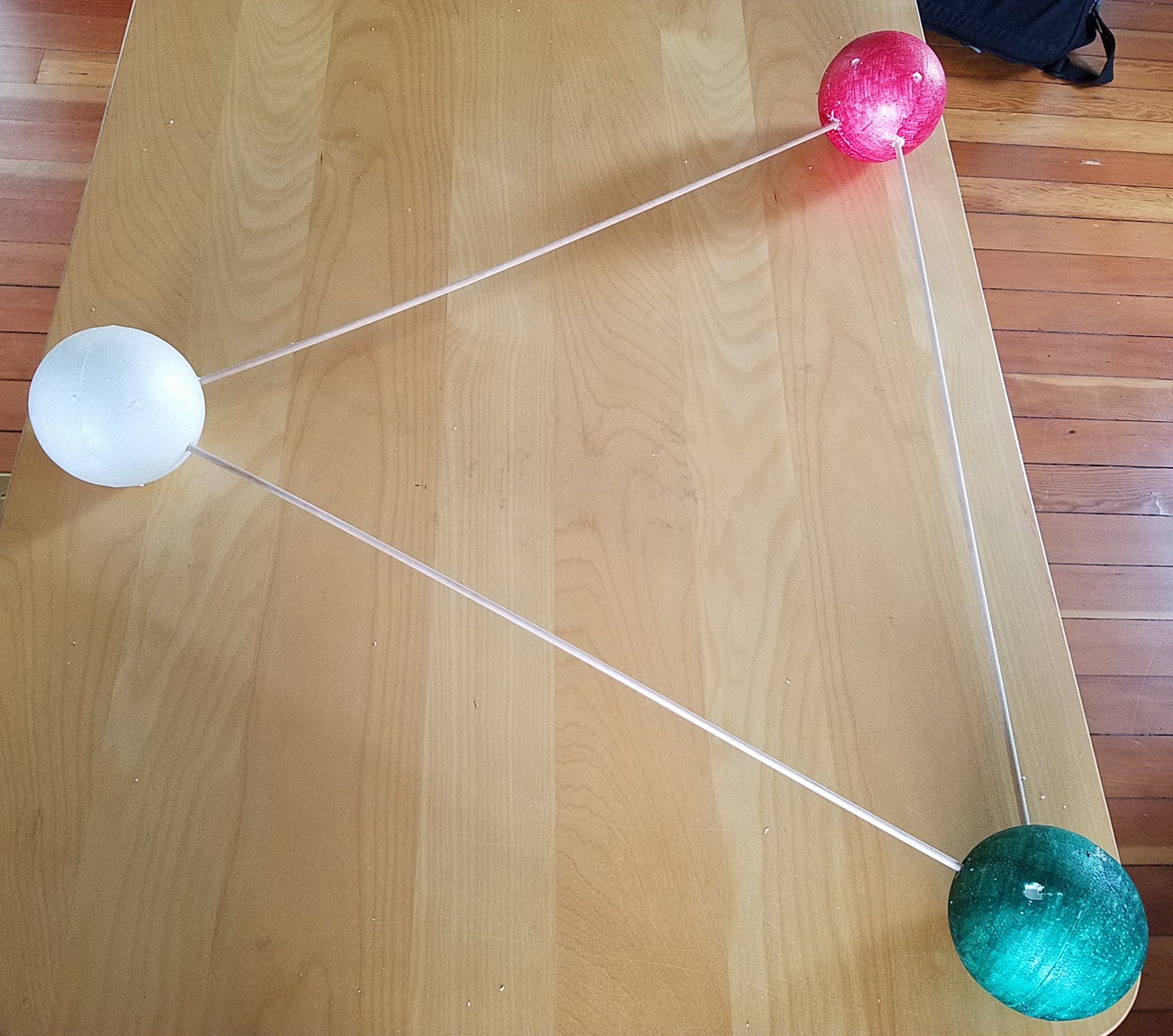
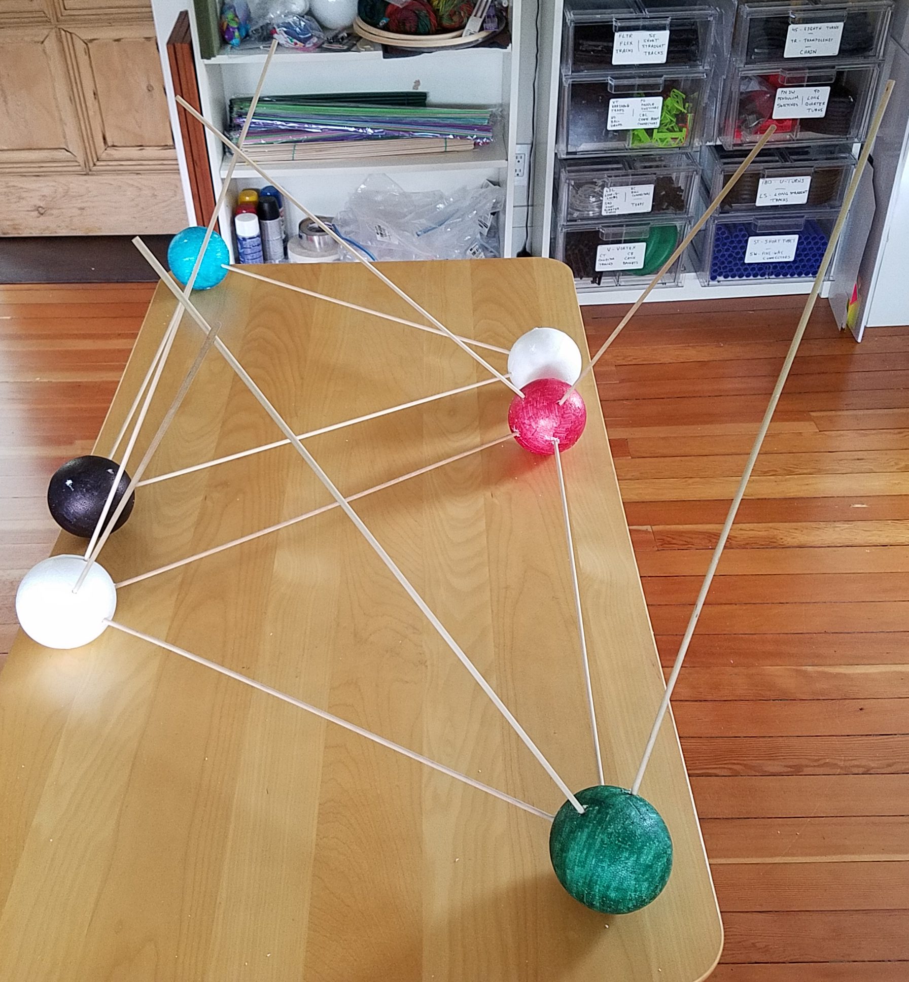
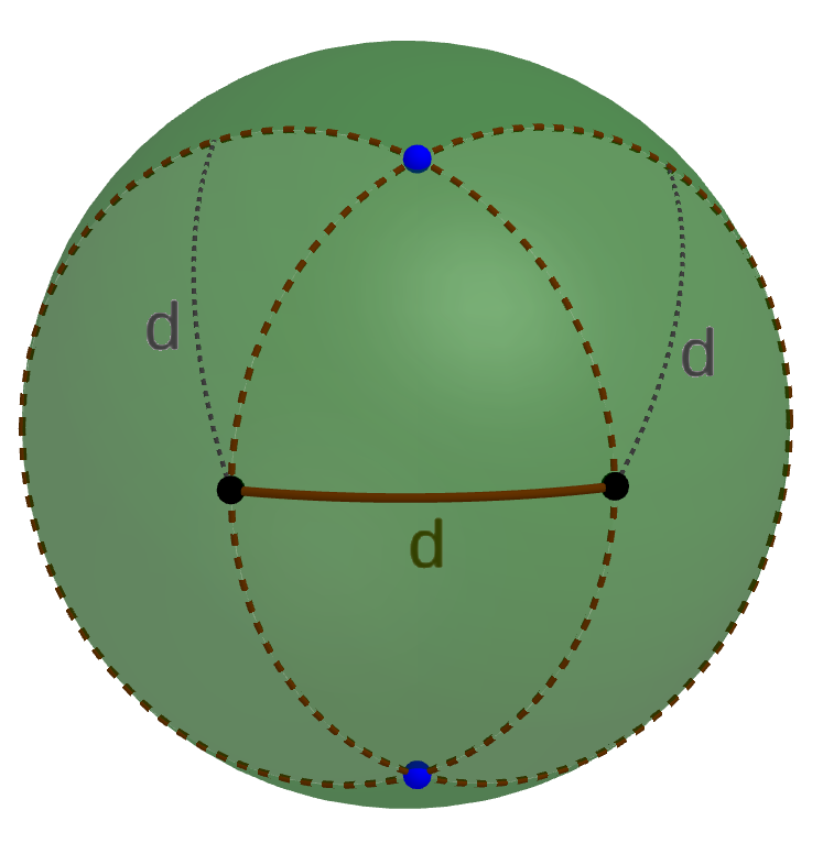
So, the possibility presented itself of using oct-tet trusses to build a large-scale model of what’s going on in the oct-tet lattice itself. The simplest subunit that shows some of the key aspects of the oct-tet lattice is a regular tetrahedron atop a regular octahedron. 
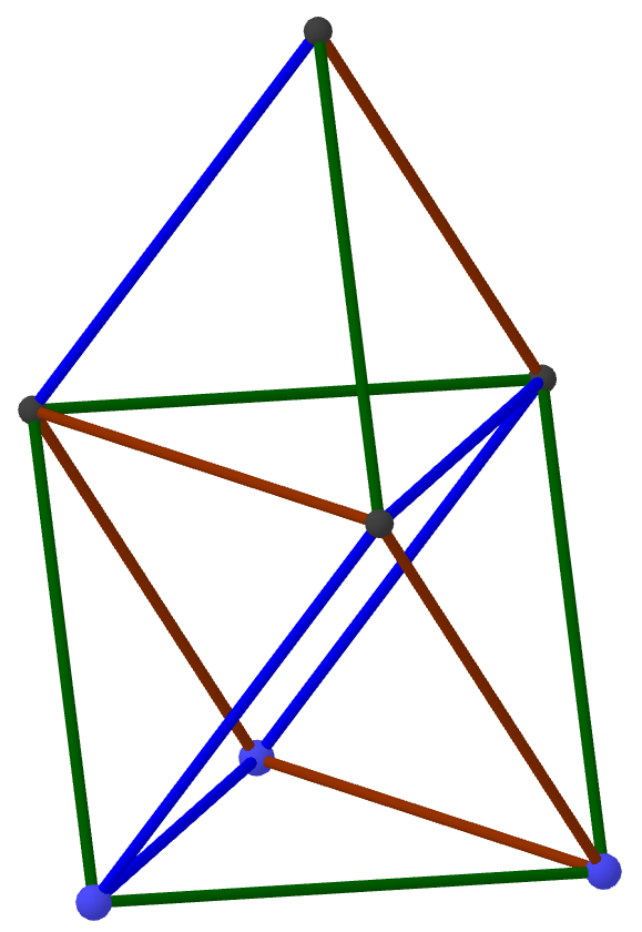
This is also about the most efficient way to achieve height in the oct-tet lattice; making just a single tetrahedron is more efficient, but to get a five-meter-tall tetrahedron, the individual trusses would have to be so long, it’s doubtful they would be sufficiently rigid.

So that’s how the plan for the Boxtahedral Tower at the Golden Gate STEM Fair was hatched. It would be a regular tetrahedron atop a regular octahedron, designed to be five meters tall. Now I just needed to make sure the trusses made out of boxes would connect the way I wanted, and I needed a model of the whole structure to double check part counts and to use in informational materials.

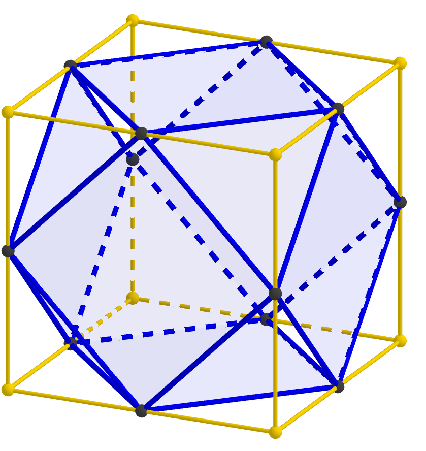
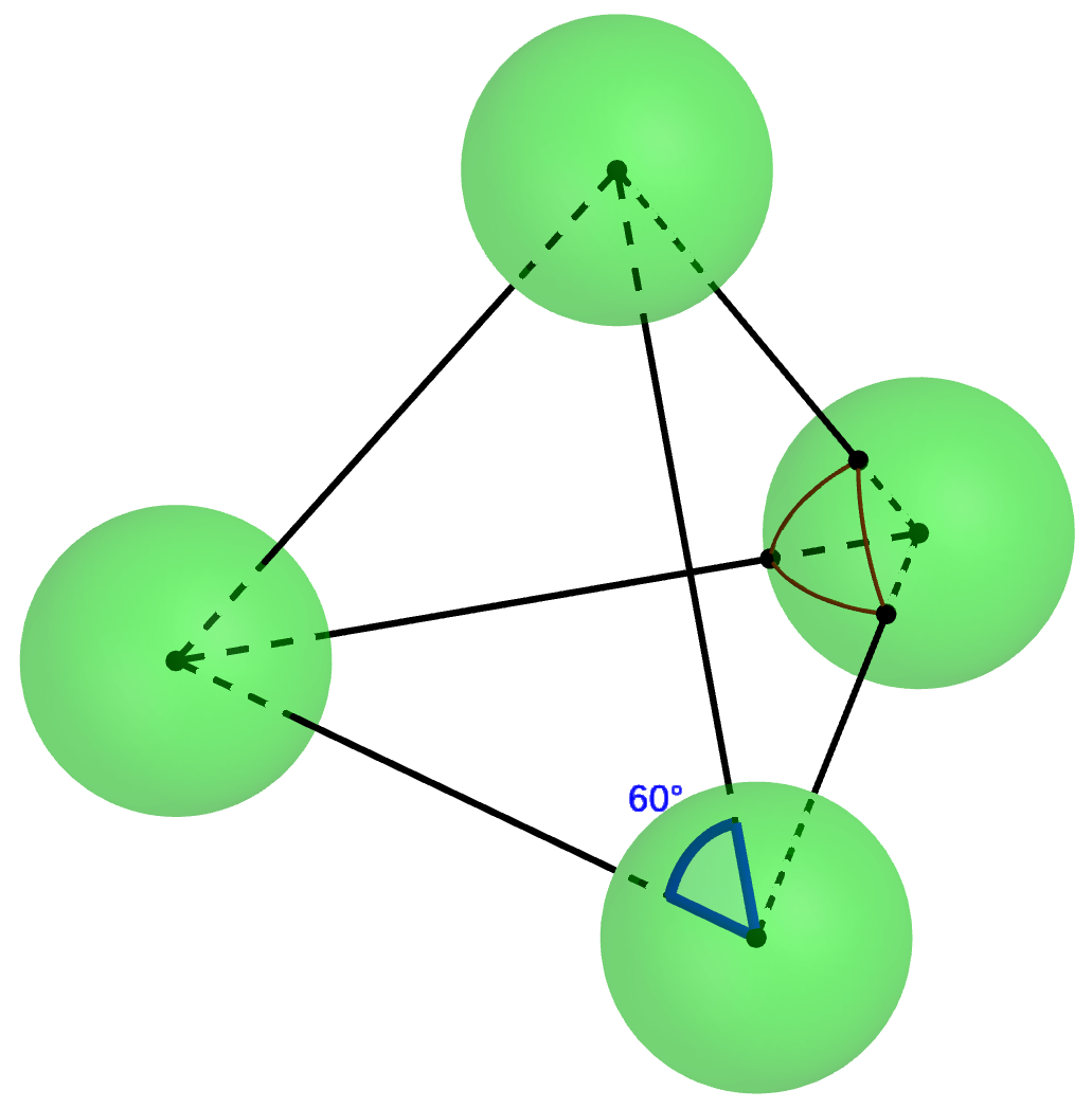
My first go-to geometry modeling tool is GeoGebra, so I fired that up and started constructing cubes. I was able to create enough to get a good view of a 60° joint between two trusses (green and purple in this shot).

But at this point, it was just taking too long per cube added, given back-of-the-envelope calculations showing there would be about a thousand cubes in all. Plus the GeoGebra interface was just beginning to slow down noticeably with so many objects. So I needed a better way to do the modeling. The answer turned out to be a free tool called VoxelBuilder. This is explicitly designed to manipulate colored cubes in a 3-d lattice, and with a bunch of rapid-fire pointing and clicking, I was able to generate this convincing rendering of the final tower.

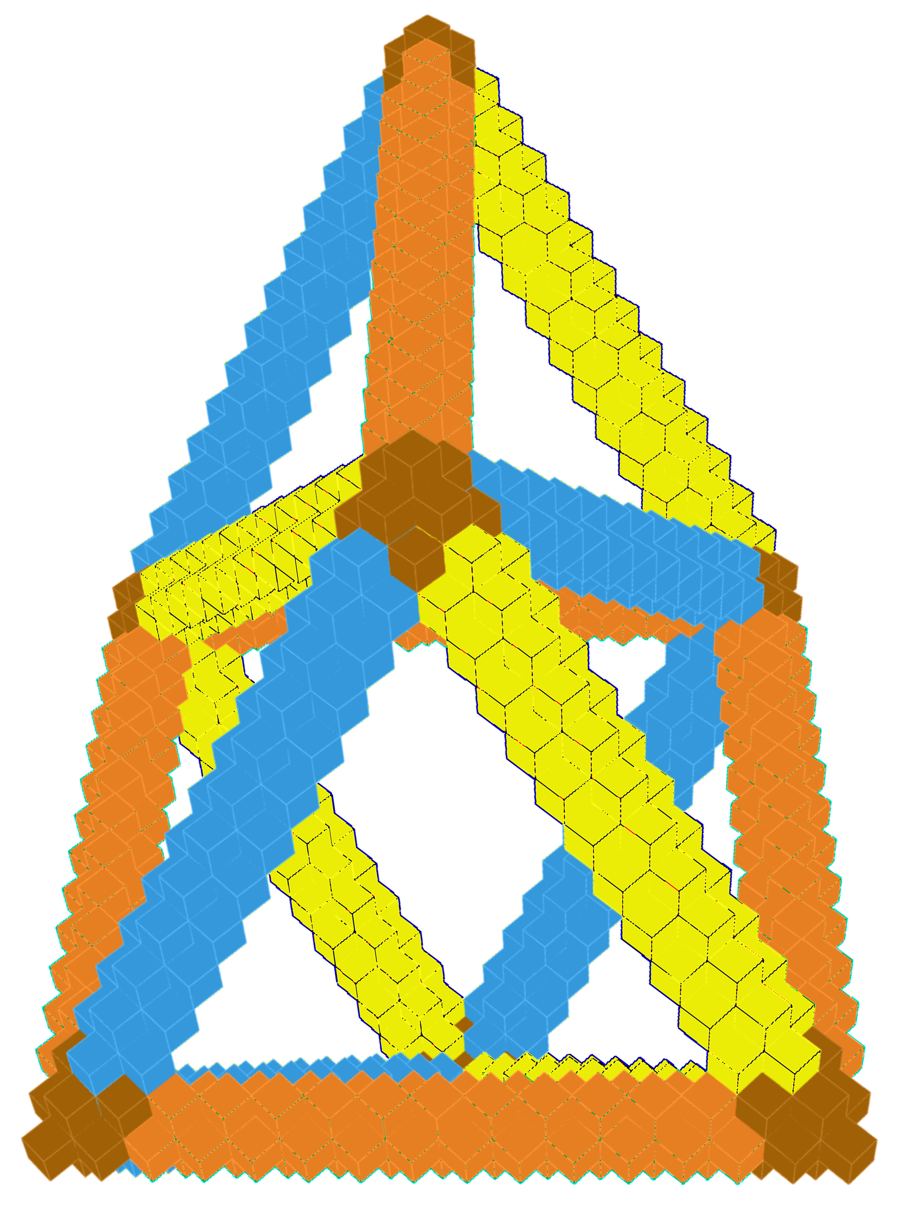
A couple of caveats: In order to get a model this large entirely onto the screen, it’s necessary to extend the limit by which VoxelBuilder allows you to zoom out. To do that, you need to install Node.js on your system, clone the VoxelBuilder Git repository onto your system, change line 351 of the file index.js from var tooFar = distance > 3000 to var tooFar = distance > 30000, run npm install; npm start in your VoxelBuilder directory, and then connect to your running copy at http://localhost:8080. Also, you should be aware that VoxelBuilder currently limits the rotations you are allowed to do on your model (basically, you can’t look at it “from underneath”), so to get the image above I had to print the model in a different orientation and then rotate the resulting image.

But these technical obstacles overcome, I had all of the pieces necessary to plan the event.

05 Apr

An Oct-Tet of Cubes

In the last MathStream post, we concluded that if you took spheres with holes at the points indicated by black dots in the diagram below, you could connect them with struts to form a lattice composed of alternating octahedra and tetrahedra.

But for building large-scale constructions, we’d like something comprised of components that are a little easier to make or obtain. The goal of this post is to show how that same oct-tet lattice can be constructed simply from cubical boxes.

The first step is to notice that we could shrink the struts to be as short as we like, or even do away with them altogether. If we had a whole lot of spheres just touching (or rather, glued together) at the black spots, they would form an oct-tet lattice.

But spheres are a bit hard to work with. Instead of thinking of them as points on a sphere, instead connect those same twelve points with straight lines and planar faces:


That produces a shape called a cuboctahedron, and what we have established is that cuboctahedra joined vertex-to-vertex form an oct-tet lattice.

But where do cuboctahedra come from? If we read much of the way down the Wikipedia page, we see the statement that “a cuboctahedron is a rectified cube.” Unraveling that word “rectified,” this statement just means that if you start with a cube, take the midpoint of every edge, and then connect the new points when the edges they correspond to connect, you get a cuboctahedron. Or we can “undo” the rectfication and re-create the cube from the cuboctahedron we have.

Therefore, connecting cuboctahedra vertex-to-vertex is the same as connecting cubes edge-to-edge, so we have established that cubes joined edge-to-edge form an oct-tet lattice. We’ve taken enough steps that this statement may now seem a bit mysterious, but hopefully this final image will help tie the whole thing together; notice that each strut in the oct-tet lattice passes through the midpoint of an edge of the cube.

05 Apr

Cuboxtahedron

Materials
6 boxtets

Here’s a very pleasant first construction to make with your boxtets. To link two boxtets together at a vertex, first make sure that the two vertices are snug up against each other — don’t leave any space. Then twist the two (long ends) of the twist ties together tightly, roughly four half-twists. (I recommend always twisting clockwise when building, as it makes taking them apart easier; then you can always twist counterclockwise when disassembling.)

To make the cuboxtahedron, first connect three boxes in a triangle. Then note that two edges of connected boxes make a sort of “V.” Turn that “V” into a triangle by adding a fourth box. Do the same with the other two “V”s formed by the original triangle, and then bring all three of the new boxes up around top where their opposites sides will meet to form their own triangle, which you should fasten together.

And voilà, you have the cuboxtahedron!

Why do I call it that? The inner shape of this structure, consisting of one face from each boxtet and the triangular spaces among them, is a well-known semiregular polyhedron called a cuboctahedron. In our case, it’s missing more than half of its faces, but nevertheless creates a surprisingly rigid, symmetric, and pleasant structure for our simple construction. If you have more boxtets, you can continue attaching more of them at the vertices — see what happens when you do!

04 Apr

Boxtets

As a result of the last couple of constructions, when Studio Infinity signed up to do a large-scale construction at the Golden Gate STEM Fair, I had the oct-tet lattice on my mind. And for a long time, I had wanted to exploit the connection between cubes and the oct-tet lattice. I just needed a way to connect cubes edge-to-edge.

Jürgen Richter-Gebert, founder of the ix-quadrat mathematics museum in Munich, Germany, suggested I could adapt the hinges he uses for making variable-angle kaleidoscopes. These hinges work extremely well, but they require a strap that at the joint changes which side of the strap is fastened to the boxes. This could probably be done by arranging the hooks and loops of double-sided velcro straps carefully, but I was afraid that the attachment would be too complex for a large-scale construction.

In another vein, I did a small construction connecting cubes vertex-to-vertex while I was the author of Math Mondays at Make: Magazine online. That connection method, however, required working on the insides of boxes in place in the structure before closing them up, which was much too intricate to scale up.

But then I realized that with a good, tight, vertex-to-vertex attachment, you can simply connect pairs of adjacent vertices to each other to create a strong edge-to-edge connection (and you can even put cubes face to face and attach all four corners to connect them that way as well).

So, here’s the procedure for making a cube with a securely fastened twist tie protruding from each vertex, ready for twisting together however you like to make cube-based sculptures. Given how they can be used to create oct-tet truss structures, I like to call them boxtets.

Materials
(for one boxtet)
cubical cardboard box
8 heavy-duty twist ties
8 large beads
packing tape

Some notes on the materials: You can buy cubical boxes online in a variety of sizes very cheaply; I used 6″ Uline boxes, which are currently available in bulk for 33 cents apiece. There are also a variety of twist ties available; if you’re planning on re-using your components, make sure to get the most heavy duty ones you can; I ordered from supplyplaza.com. Six to eight inches long work well; I’d recommend longer if you’re doing a large construction, even though the long wires sticking out look a bit awkward at first. Longer wires are just easier to get a hold of and pull tightly, and large constructions require very tight connections. Finally, I recommend beads at least 15 mm in diameter, preferably a bit larger, as they are what keeps the twist-ties from pulling out of the corners of the boxes. You want to use large-hole beads to make it easier to feed the twist-ties through.

Here’s how to put a boxtet together. First, you need to attach the twist ties to the beads. Insert a twist tie into a bead so that one end protrudes about twice the length of the bead, then bend it back around and twist it to itself, making sure to (a) twist it tight against the surface of the bead and (b) leave a small “tail” extending from the twist as well as the main long section of twist tie. Here’s what you should get.

When you have eight done, it’s time to assemble the boxtet. Basically, you are assembling the box as usual, except before sealing up one side, you slip a bead down the slit between the flaps as shown at right — note that both the long end and the short “tail” of the twist tie are on the outside of the box. The purpose of the tail is to keep the bead/twist tie combination from sliding all the way into the box so that the twist tie is no longer accessible. Make sure you have beads in all four slots (as on the left) and then tape it up normally, like so (one piece of tape should suffice, as there’s essentially nothing inside the boxes).

Insert beads in the other side of the box and tape that up too, and you have your first boxtet.

In the next post we’ll see what we can build with them.

Update: At the Golden Gate STEM Fair, some participant(s) figured out a better way to construct a Boxtet.

04 Apr

Octahedron Too

So when I was doing the math for the styrofoam-dowel tetrahedron, I noticed that locating the holes

Materials Tools
12 3/16″ dowels thumbtacks
6 4″ closed-cell
styrofoam balls
thread, wire,
or thin twist-tie
optional markers ruler
drill with 9/64″ bit

necessary for making a regular octahedron should be easy too. Naturally, having done the theory, it’s hard to resist actually building the thing. The materials are exactly the same as for the tetrahedron, just the quantities are different. In fact, you can re-use two holes from each of the balls you made for the tetrahedron.

Then you have to measure out two different lengths of thread or twist tie, tied from one shaft of a thumbtack to another. The first is 2.1 inches, just like before; that’s the length of the sides of the square of holes we’re going to drill. The second is 3.15 inches, for the diagonal of the square. (If that value is ringing bells in your brain, you are absolutely right: if you chase down all of the math that went into this, we’re going for exactly π inches from pin to pin here, but the accuracy of this process is way below 1/100 of an inch, so even 3 1/8″ is good enough, for example.)

For each ball, you start with two arbitrary holes separated by the shorter distance (which can be previously used holes). Then you scratch (appropriate arcs of) circles of each of the two radii from each of those two holes. They should intersect in pairs (the closer arc to one hole with the farther arc from the other) to create four points for drilling arranged in a square on the surface of the sphere. Here’s a picture of the two thumbtack setups of the two different lengths, and one ball with the scratches in place.

Once you’ve drilled all four holes in each of the balls (less any holes you might be re-using), it’s time to assemble. I recommend making two triangles first (one pictured on the right), ensuring that all pairs of unused holes point upward. Then use the remaining six dowels to insert in the remaining holes of one of the triangles, leaving six free ends up in the air.

Finally, flip over the other triangle and connect it as the top face, producing the final octahedron:

Theoretically, exactly the same procedures could be employed to make a section of the oct-tet lattice, but that would require a lot of scratching and drilling…

04 Apr

More Spherical Construction

The ease with which we could draw an equilateral triangle on the sphere naturally leads to wondering whether other constructions work out so nicely. For example, can we construct the square of points that would be needed to locate the holes for building a regular octahedron from styrofoam balls and sticks?

Since the central angle between any two adjacent vertices of the square is again τ/6 = 60°, the sides of the square are the same length as the triangle’s sides in the previous construction. So let’s just look up the geometric construction of a square and use that on the sphere. Unfortunately, you immediately hit a snag: the first step is to “extend the line segment PQ.” And I don’t know of a really practical way to extend line segments on a sphere. You could try a flexible ruler, but it’s hard to get it lined up and to draw with it in place. Or you can make three equilateral triangles that all share the same vertex; then the side of the third one extends the original one. That’s fine in theory, but in practice it’s a lot of work and it’s easy for small errors to accumulate, leaving the sum of the three angles meeting at the vertex a bit different from 180° = τ/2.

So to make things much easier, we will use a special property of this particular square. As you can see in the picture, the regular octahedron can also be viewed as a square bipyramid. That tells us that the central angle between points A and C diagonally opposite on the square we want is τ/4 = 90°. And that in turn means that the diagonal of the square on the surface of the sphere is exactly 1.5 times as long as the side of the square. Contrast this to the situation of a square in the plane, where the diagonal is the much more computationally difficult √2 times the side of the square, but beware! This relationship does not hold for all squares on the surface of a sphere. Indeed, the ratio of diagonal to side length of spherical squares ranges from √2 to 2, and in fact, you can determine the side length of a spherical square from just that ratio (and the radius of the sphere).

But for the particular square we want, we do have this lovely relationship that the diagonal is 1.5 times the length of the side, and so we can find the other two corners just as we did for the equilateral triangle, simply using a thread of length d for one arc and 1.5d for the other arc. So building a regular octahedron should also be quite feasible.

We can go a bit further than this. If you play around with constructing these squares and triangles, you will find that alternating them completely covers the sphere. In other words, there are just twelve points on the surface of the sphere so that each one is a vertex of two equilateral triangles and two squares, alternating. That’s a pretty special structure, and it allows the existence of a very strong framework filling space called the oct-tet lattice consisting of alternating octahedra and tetrahedra.

04 Apr

Ruler and Compass on a Sphere

For this project, I needed to figure out (a) where should the holes be in spheres to connect them by straight lines to form a regular tetrahedron, and (b) how to locate those points on a physical sphere. The diagram makes part (a) fairly straightforward. We can see that the angle between any two holes (as viewed from the center of one of the spheres) should be 60°, the angle at each vertex of an equilateral triangle. And since 60° is one-sixth of a full circle (or an angle of τ/6, as the tauists point out), we can find the required distance d between any two holes on the surface of a sphere of radius r to be d = rτ/6, or approximately d ≈ 1.047r.

Now, how should we actually locate the points? As you can see from the diagram, they form a sort of “spherical equilateral triangle,” each point the same distance from each of the other two. And as you may recall, it’s pretty easy to construct an equilateral triangle in the plane. Fortunately, exactly the same procedure works on a sphere: First, select any two points a distance d apart on the sphere. Then using each of the two points as center, trace out a spherical circle with radius d on the surface of the sphere. (In practice, you only need a small section of each circle in the vicinity of where they’re going to intersect.) Each of the two points at which those two circles intersect represents one of the two possible locations for the third vertex of the desired triangle.
Moreover, it’s easy to perform this construction in practice. And mathematical curiosity makes us wonder: if it works for triangles, will it work for other constructions as well?

03 Apr

Marshmallow Shapes Grown Up

Recently a friend of mine was giving a (math) talk and wanted as a prop “a large tetrahedron with the vertices emphasized.” This seemed like a natural for Studio Infinity, so the assignment was accepted. And my immediate first thought was of the classic marshmallow shapes that you may have made in school or Girl Scouts or wherever.

Unfortunately, for use at the front of a large room, this would have to be scaled up considerably, and I didn’t relish the thought of trying to deal with humongous marshmallows.

Materials Tools
6 3/16″ dowels,
all the same length,
e.g. 2 feet
thumbtacks
thread, wire,
or thin twist-tie
4 4″ closed-cell
styrofoam balls
ruler
permanent markers,
if you want to
color the balls
drill with 9/64″ bit

So the natural substitutions were two-foot-long 3/16″ dowels for the toothpicks, and 4″ styrofoam balls for the marshmallows. (Use closed-cell styrofoam, it’s much more stable and easy to work with than open-cell.) However, unlike marshmallows, styrofoam balls aren’t squishy and forgiving, they’re rigid and brittle, and you can’t really just insert a blunt dowel directly into the fairly hard surface of a closed-cell styrofoam ball. If you want your corners to be colored, do that before you begin the construction (it will also help the scratches you make in the next step show up well).

So the first thing you need to do is locate the three points where a dowel will be inserted into each styrofoam ball. Fortunately, analyzing the geometry shows us how to find those points. So get out two thumbtacks and a piece of thread. Tie the thread to the post of each thumbtack so that the length of the thread between posts is 2.1 inches. Stick one thumbtack anywhere you like on the ball, stretch the thread taut along the surface of the sphere, and stick the other thumbtack in (again, anywhere you like, so long as the thread is taut). Now gently lift one thumbtack out of the ball, and keeping the thread taut against the ball, scratch a circular arc roughly where you expect the third hole to go. Then re-insert that thumbtack in its original hole, and do the same with the other thumbtack. The two thumbtack holes and the the point where the two scratched arcs intersect are the three locations to insert the dowels.

To finish the assembly, drill holes from those points straight toward the centers of the spheres, most of the way to the center, between 1.5 and 2 inches deep. Try to make your holes uniform in depth. Repeat the process of locating and drilling holes for the other three balls. Now it’s just a matter of connecting the balls together with the dowels. The holes are deliberately smaller than the dowels so that there’s a tight fit when you insert them — push firmly. I recommend building a triangle first, then inserting the other three dowels pointing up.

Then add the last ball to complete your tetrahedron. (And the tetrahedron shown below did in fact appear in my friend’s talk.)