07 Nov

Stretching the Point

So far, we’ve created a lot of interesting small models of tensegrity structures. However, for doing public programs of the sort Storm King Art Center was planning, it’s always helpful to be able to build much larger models of things. Building giant models seems to get the ideas across more vividly, engage visitors more thoroughly, and be just plain fun.

So how to stretch the scale of these little models? I’ve experimented with using dowels instead of coffee stirrers and giant rubber bands, or sections of PVC pipe and bicycle-rack bungee cords with hooks, and several other similar systems. But Warning!: Studio Infinity does not recommend that you try any of those materials. They all share one dangerous flaw: If one connection slips, it’s all too easy for a portion of the structure to turn into a sort of crossbow, ejecting one of the rigid compression members at high velocity and potentially striking one of the people working on the structure. There is a significant possibility of injury. Do not attempt to build such structures.

Now, why wasn’t this much of a problem for Ken Snelson and his crew when they were building his sculptures? The answer is that he connected his compression members (generally large aluminum tubes) with steel cable. The steel cable has very little give, and hence there is very little opportunity to catapult one of the tubes; there will be very little motion even if tension is accidentally suddenly released on one of the cables.

However, the flip side of using a tension material like steel cable is that the tension members have to be measured very exactly for the sculpture to adopt its desired form. Too long, and the sculpture will simply hang slack. Too short, and there will be no possible chance of assembling the structure. We use stretchy materials for our models because they are very forgiving: if a section of rubber band is too short, we can just stretch it a bit extra to get the model together, and then adjust lengths/tensions afterward. That method is not possible if you’re using steel cable connections.

Materials Tools
15 cardboard tubes Drill or drill press
5/32″ bungee cord 7/32″ drill bit
box cutter

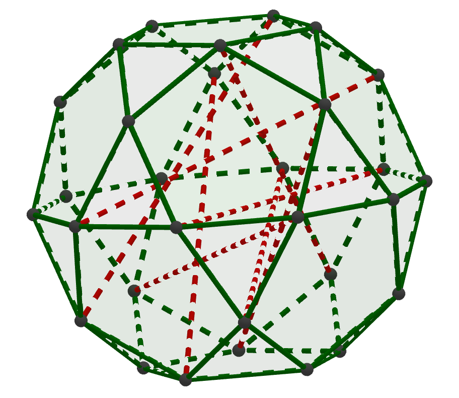
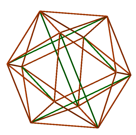
So here’s the construction method I shared with staff at Storm King Art Center. Let’s make a set of large pieces for an icloseidodecahedron. The key is to use cardboard tubes as the compression members: they’re very light, have no hard or sharp corners or edges, and yet are rigid enough to take a lot of compression from the attaching cords. You can get the cardboard tubes as mailing tubes from shipping supply companies, or as poster tubes, or even as the central tube of gift-wrapping paper (but note that often the latter kind of tube has thin walls that might buckle under compression). For the tension members, you can buy a spool of thinner-profile 5/32″ marine bungee cord. That material helps with safety as well; it just doesn’t pack the same elastic punch as its thicker cousin typically used for bungee cords with hooks.

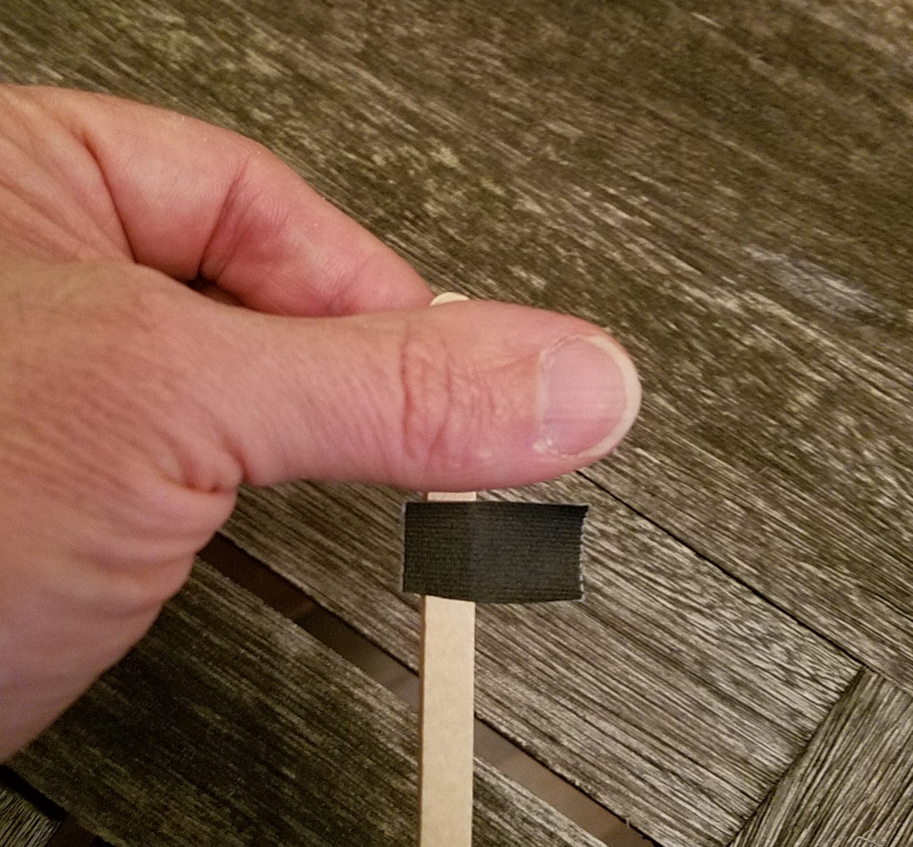
Now, you’re going to need to drill through the walls of the cardboard tubes in order to fasten the bungee cord. To prevent the tube from rolling around as you drill it, you’re going to need to fashion some sort of a jig to hold the tube in place. You can either use whatever triangular blocks you happen to have lying around (hurray for saving the leftover bits from earlier 3-D printing projects), or you can make do with rectangular blocks as well. I recommend a drill press for this task if you have one, as you will get neat pairs of holes directly opposite each other on the cylinders. However, you can certainly make do with a hand drill, as this setup shows. You just may find that your holes don’t line up quite as well.

As far as what size of tube you should use, that’s really limited only by what you can find and handle without difficulty. You want a fairly narrow tube, with strong side walls. I have tested nominal 2-foot by 1.5″ mailing tubes (which are actually almost 25 inches long) and the center tubes of 30-inch wide wrapping paper (which again are a bit longer than 30 inches).

Once you have your jig set up and your tubes ready, the drilling is simple. You just want to make two parallel pairs of holes at each end of each tube. One pair should be two inches from the end of the tubes, and the other pair should be an inch and a half from the end. After you have drilled both holes, you want to create slits (on both sides and both ends of each tube) from the hole closer to the end of the tube leading out to the end of the tube. To make the slits, insert a box cutter in the hole with the blade pointing away from you and toward the end of the tube, and push the cutter away from you out to the end of the tube.

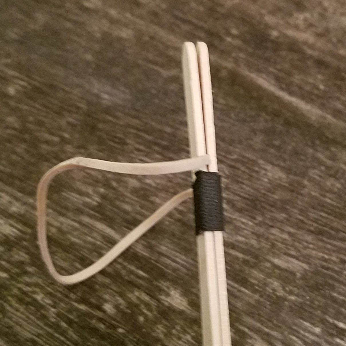
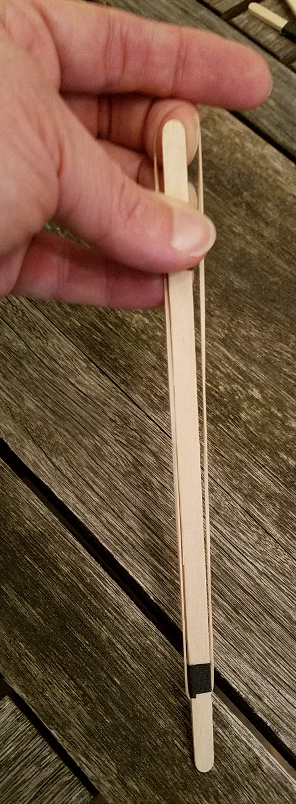
Next, we need to string the tubes with the marine bungee cord. For the two-foot mailing tubes, you need a 34-inch piece of the cord; for the longer tubes, a 42-inch piece worked well. Thread the cord through both holes at one end of a tube, and center the tube on the piece of cord. Then thread each end of the cord back into the tube via the hole on the opposite end of the tube but the same side, so that the cord lies flat along each side of the tube. To secure the cord, reach into the tube where the two loose ends are, pull both ends out as far as you possibly can, and then tie an ordinary overhand knot in the doubled cord. When you let go, the knot will disappear into the tube. If there are bits of bungee cord sticking out from the end of the tube, just stuff them inside.

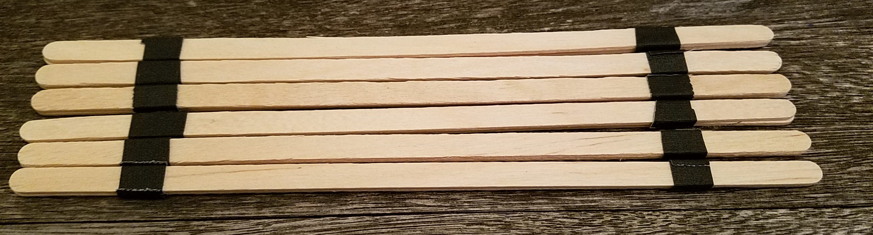
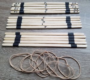
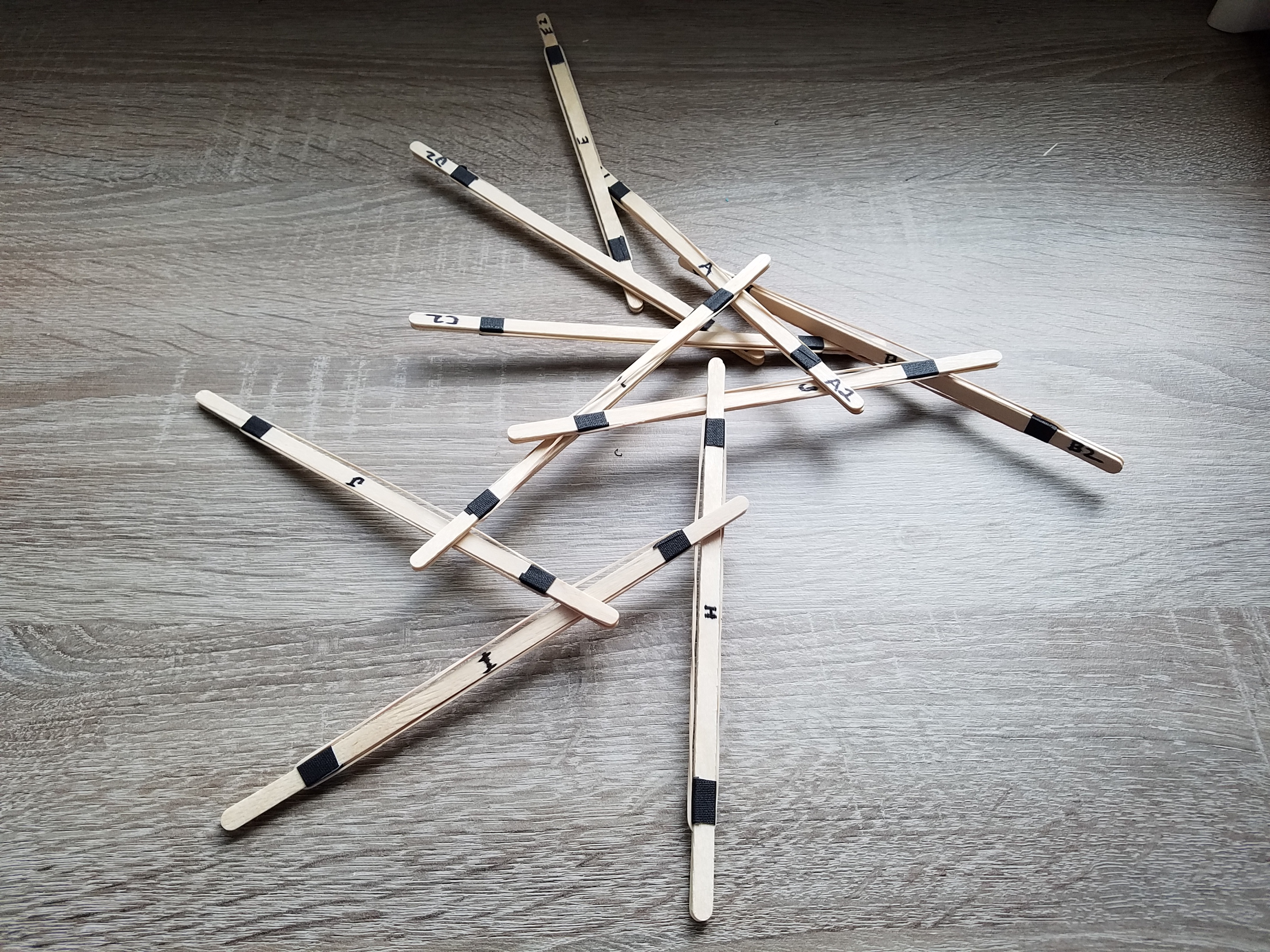
When you’ve accumulated a pile of 15 struts strung with bungee cord, you’re ready to build.

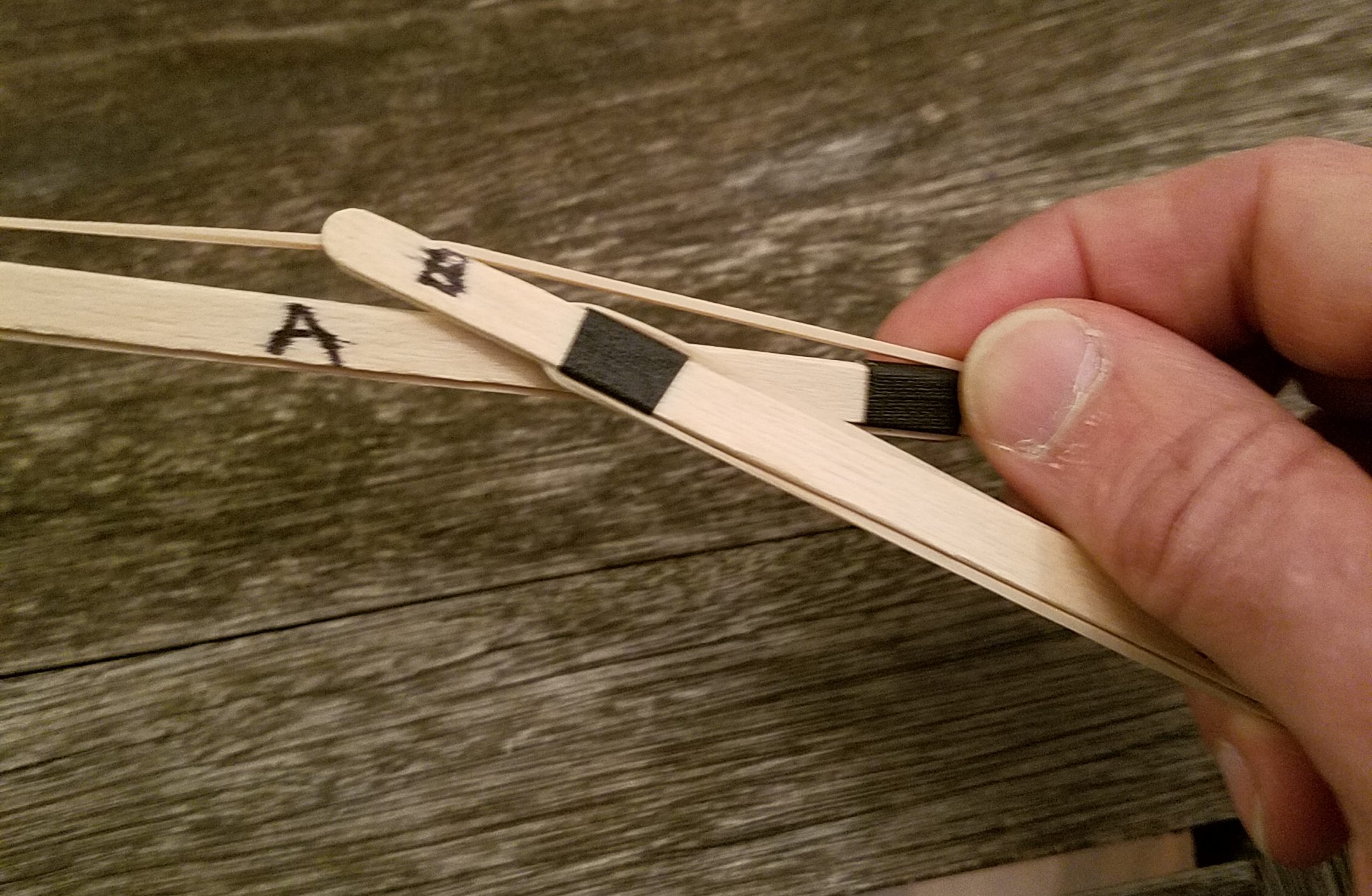
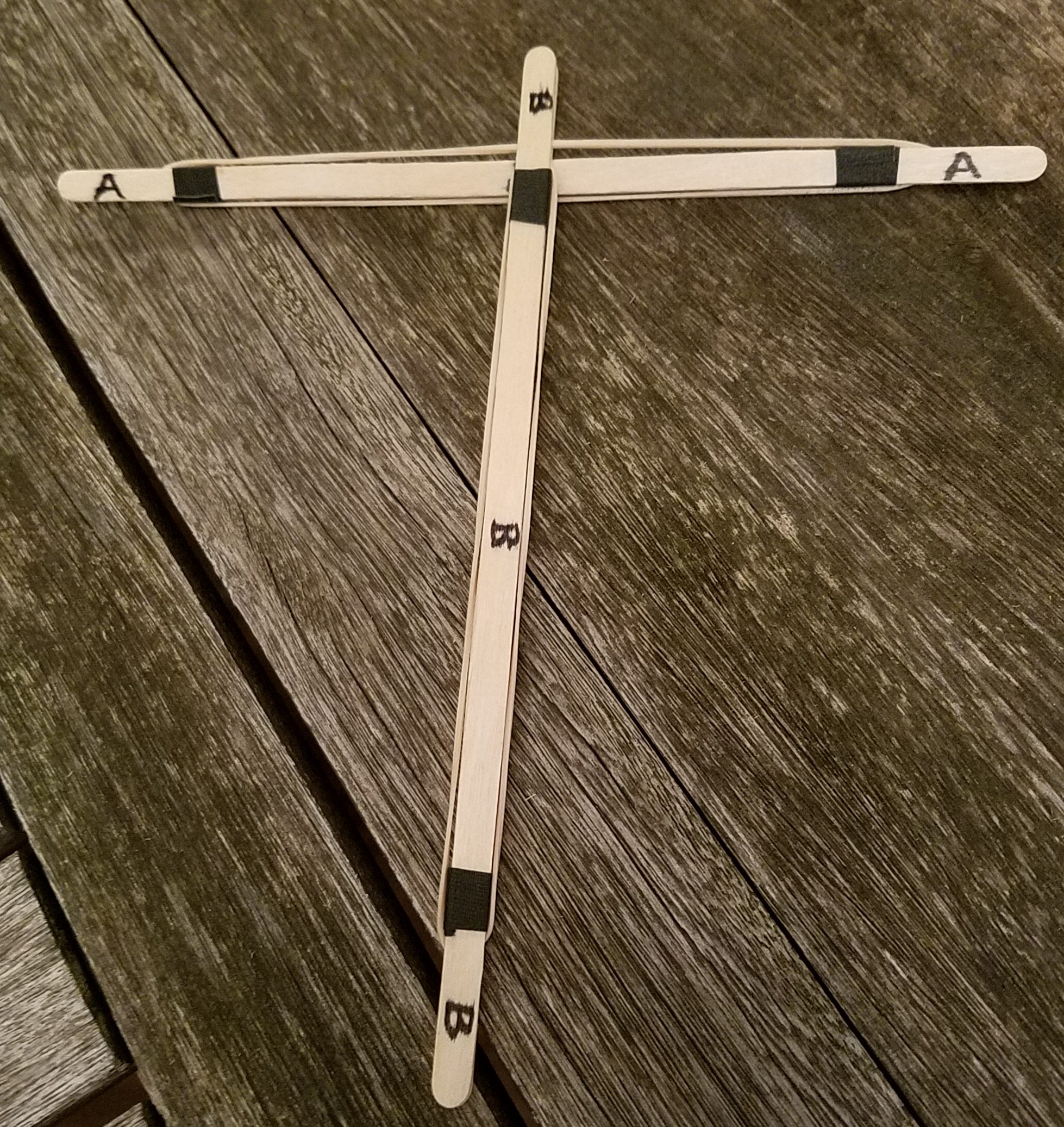
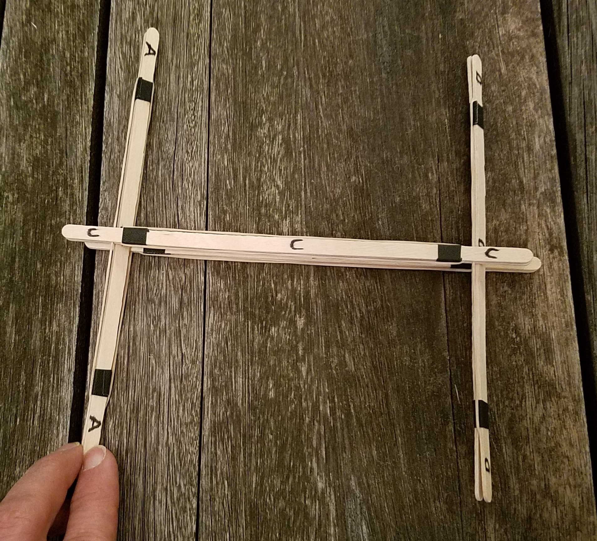
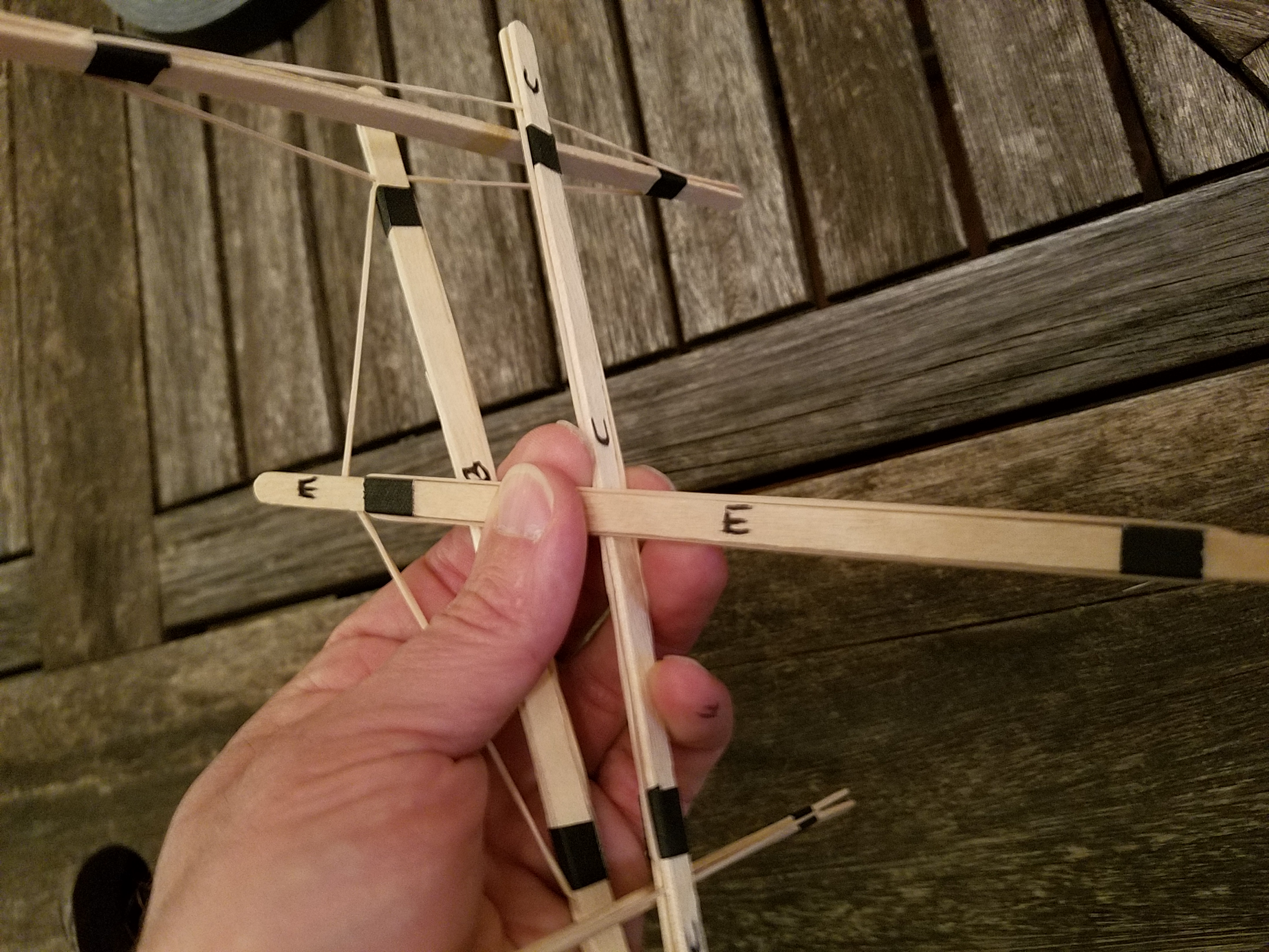
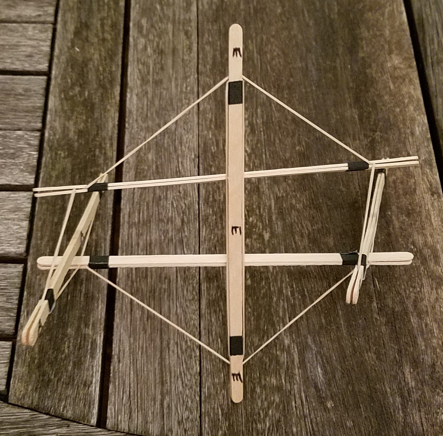
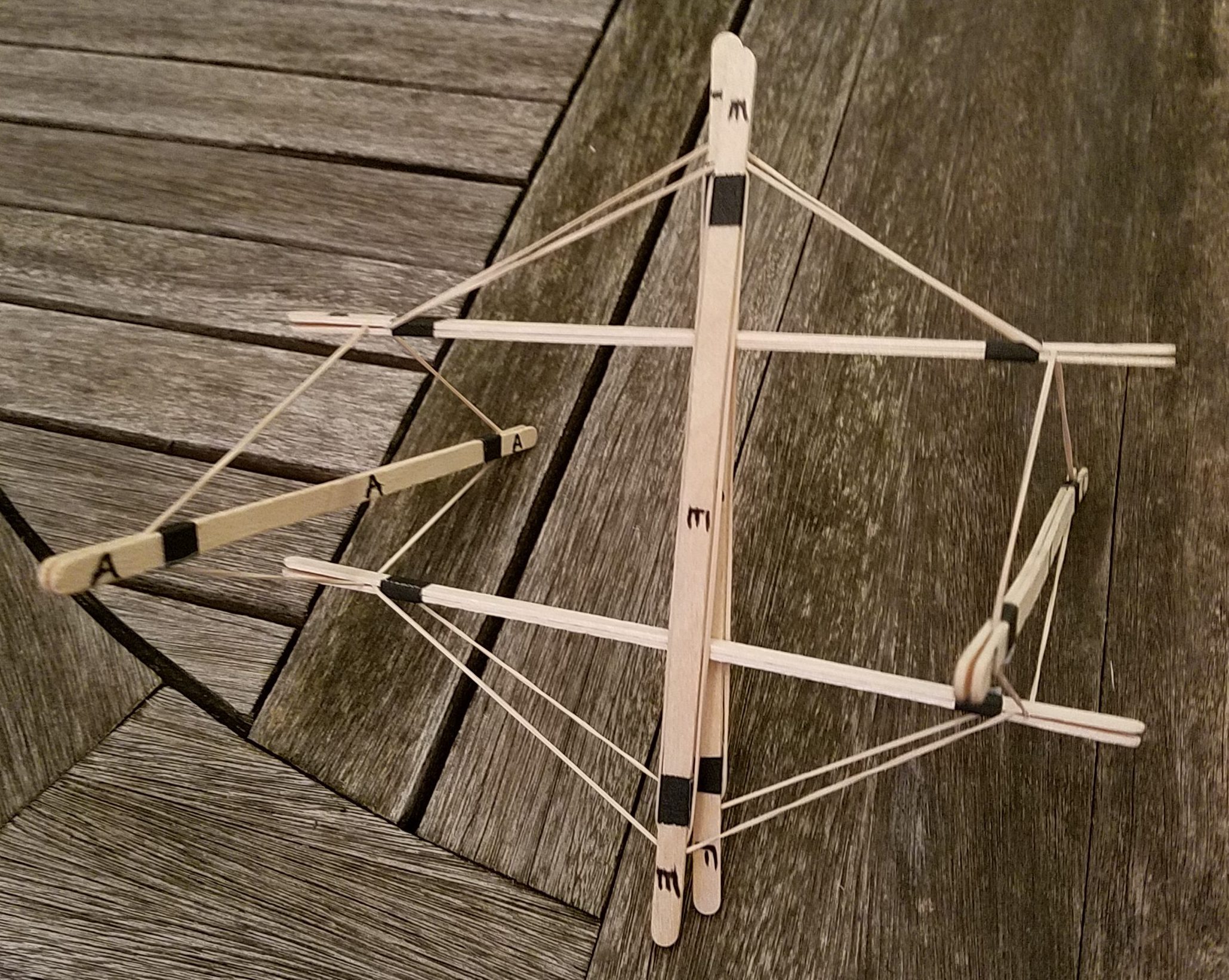
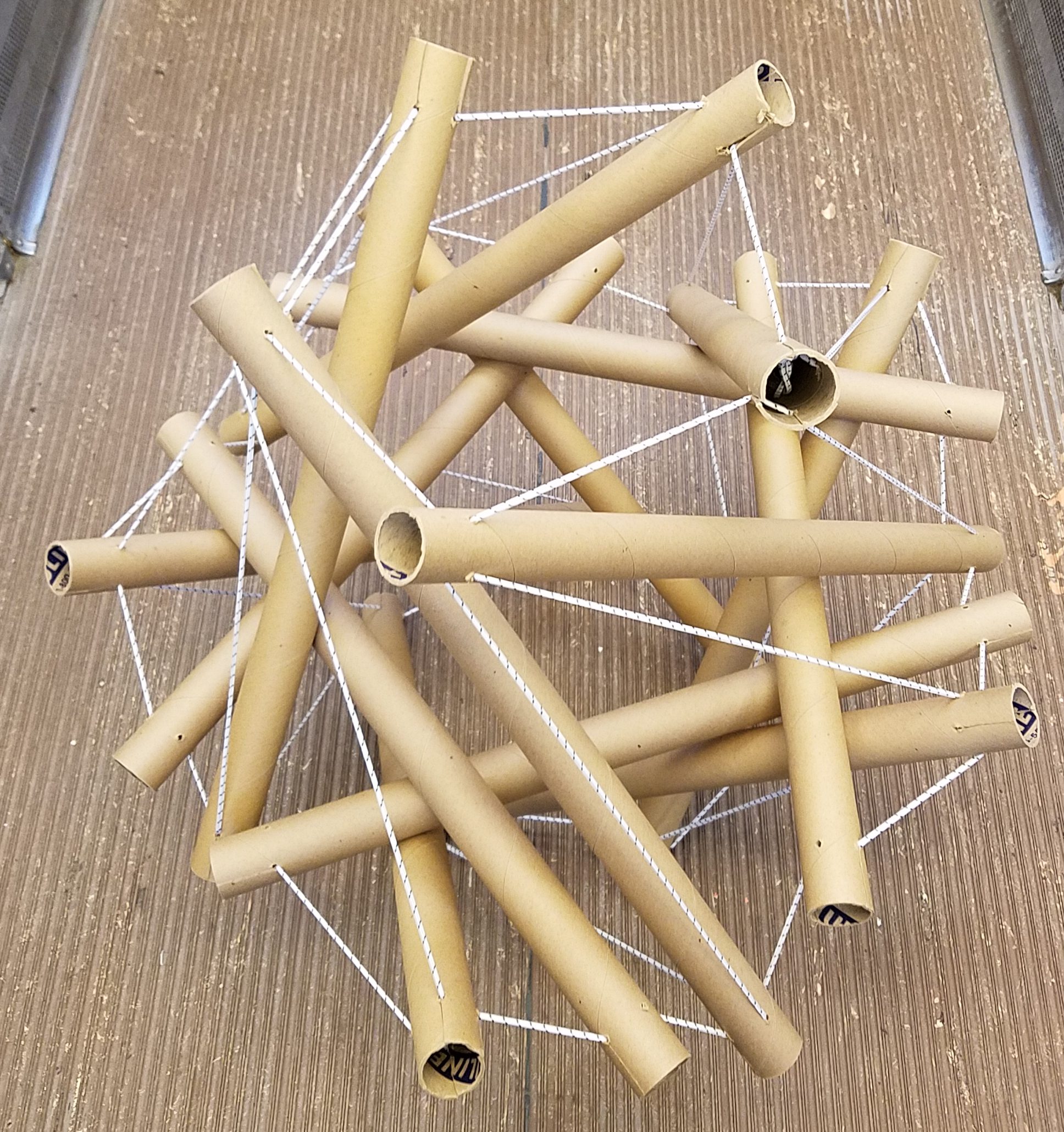
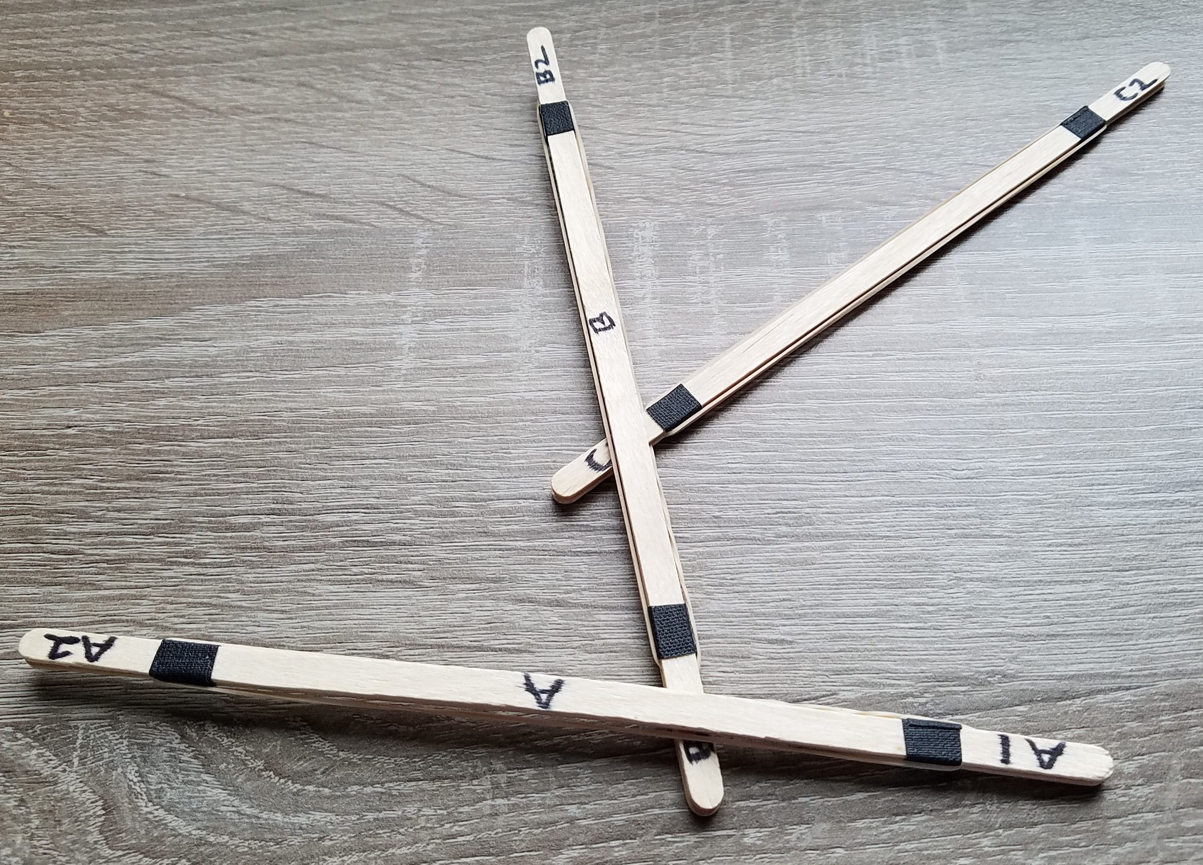
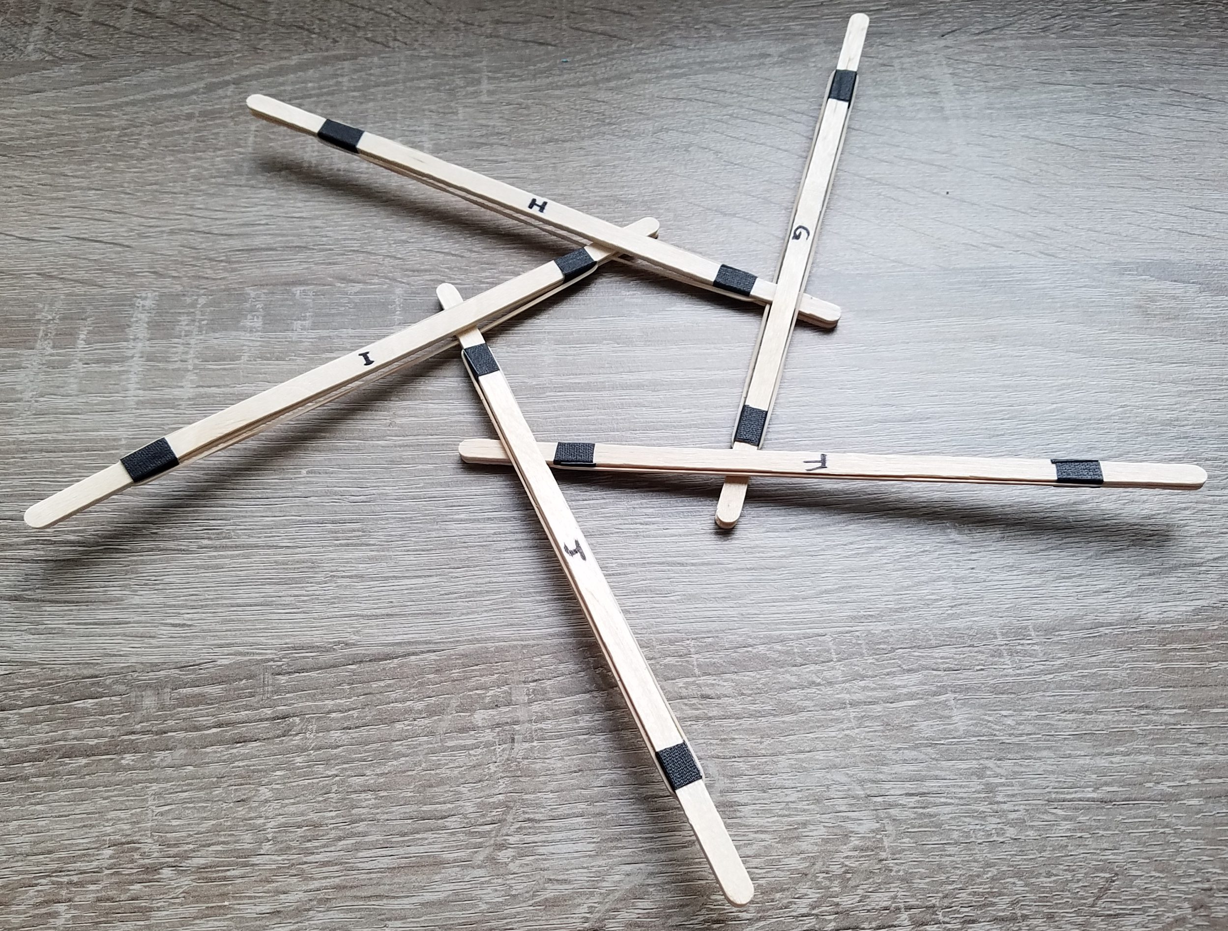
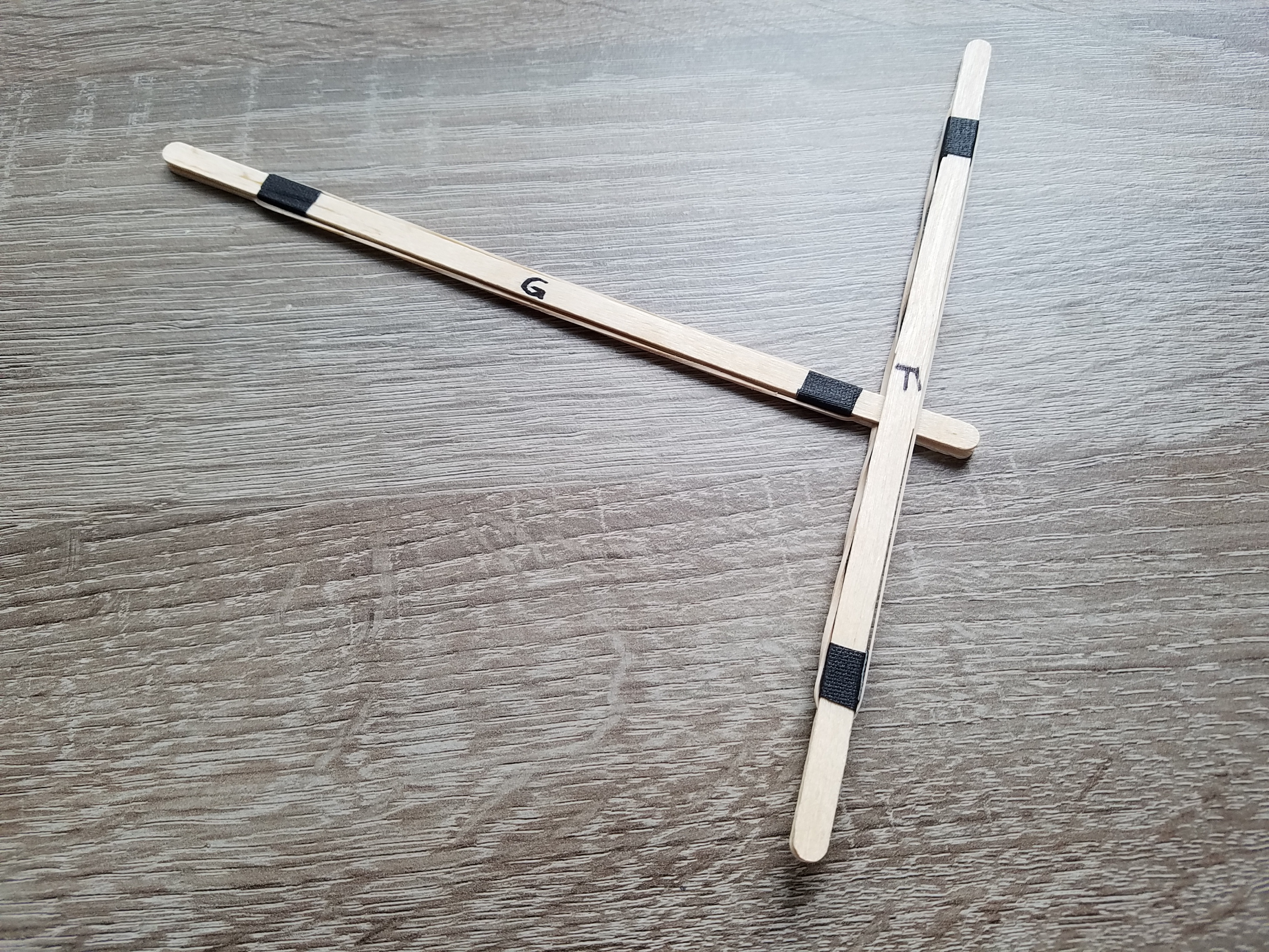
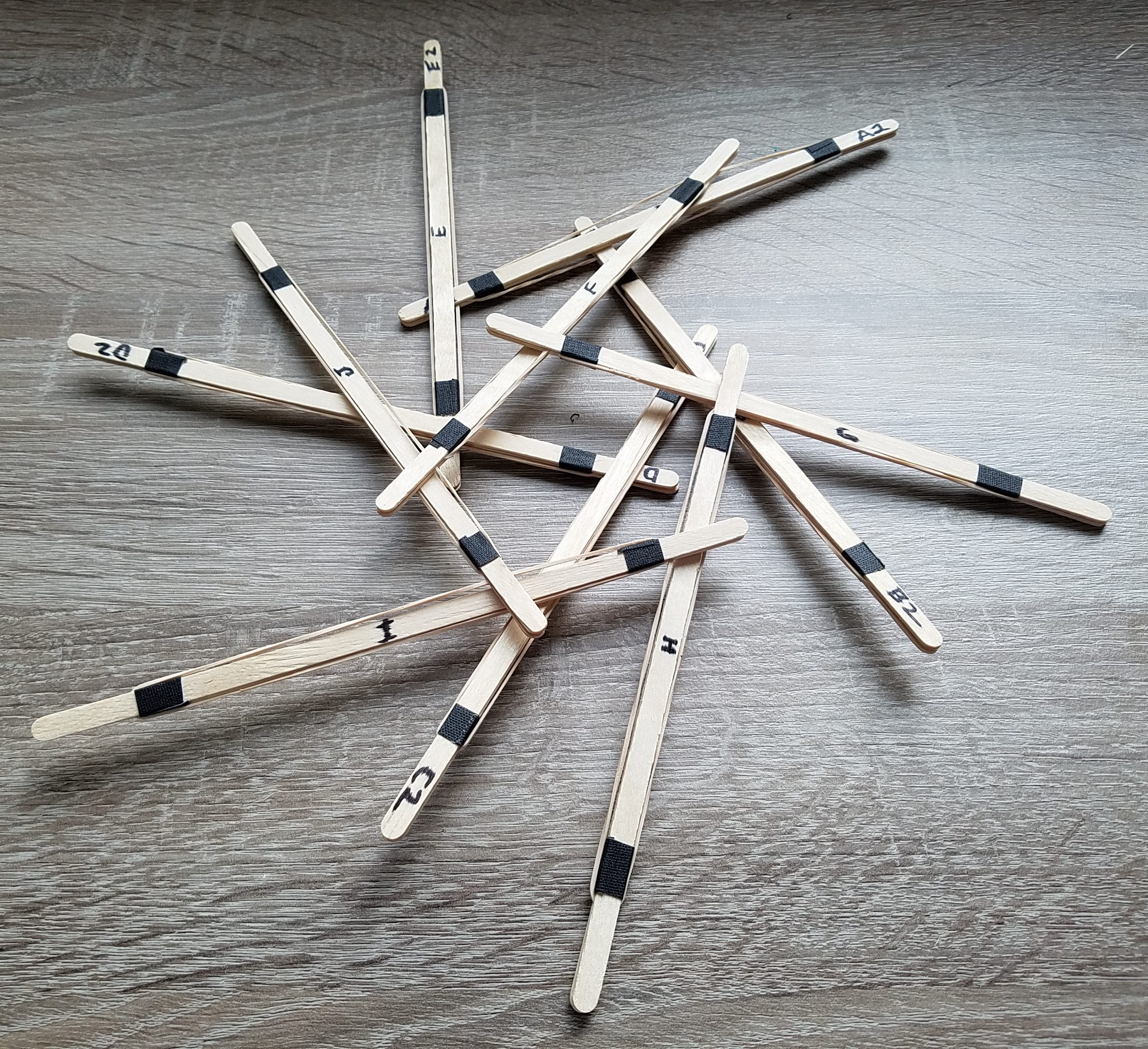
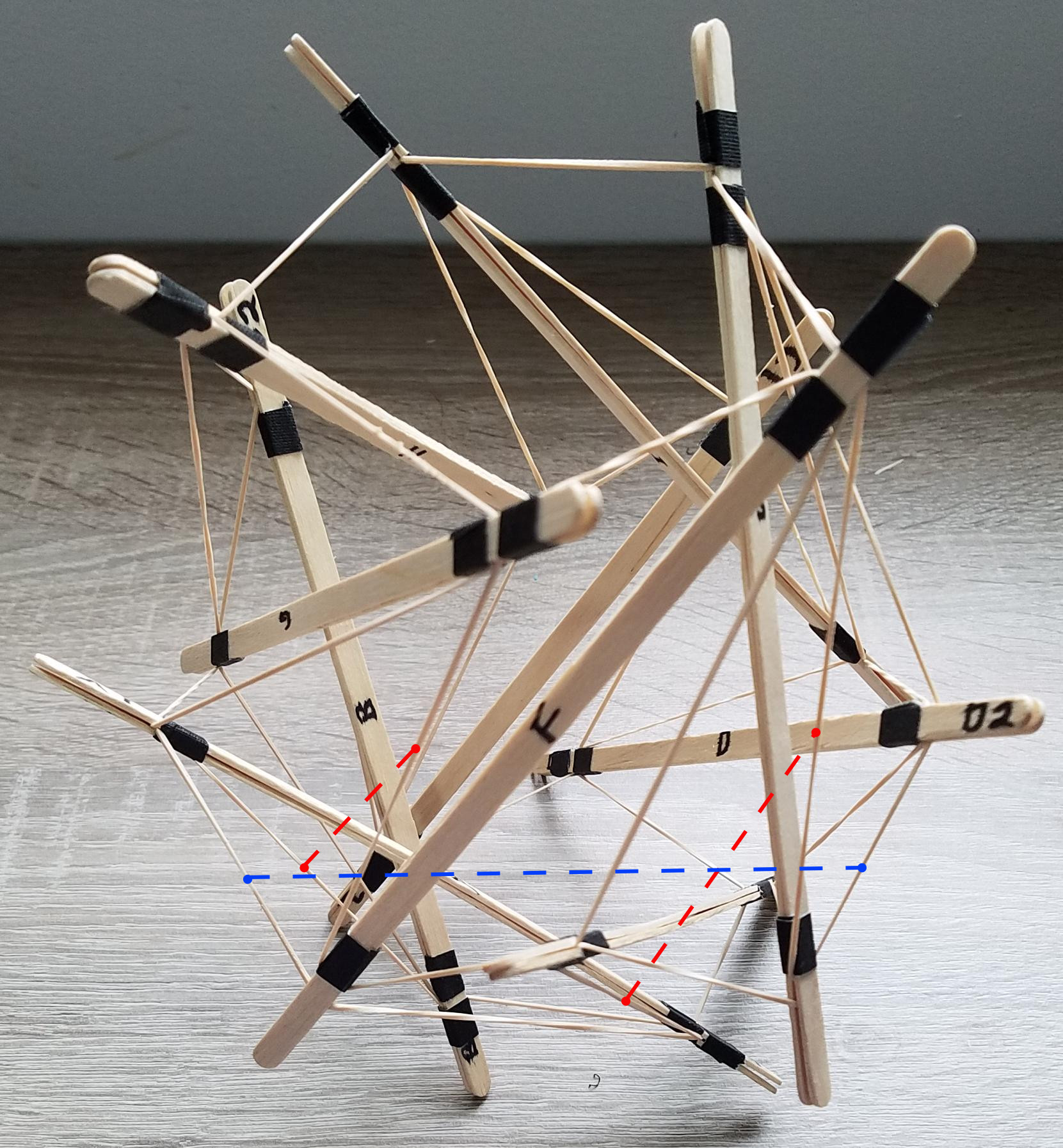
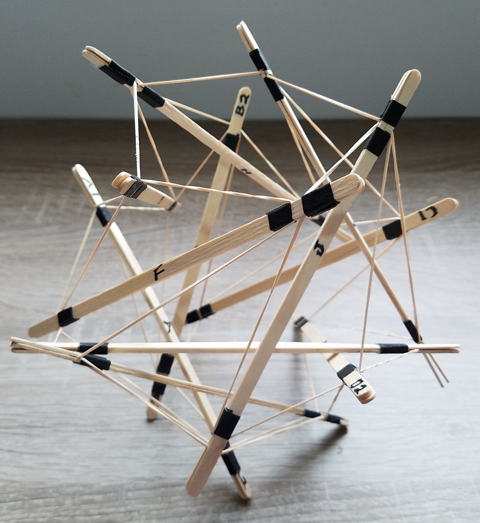
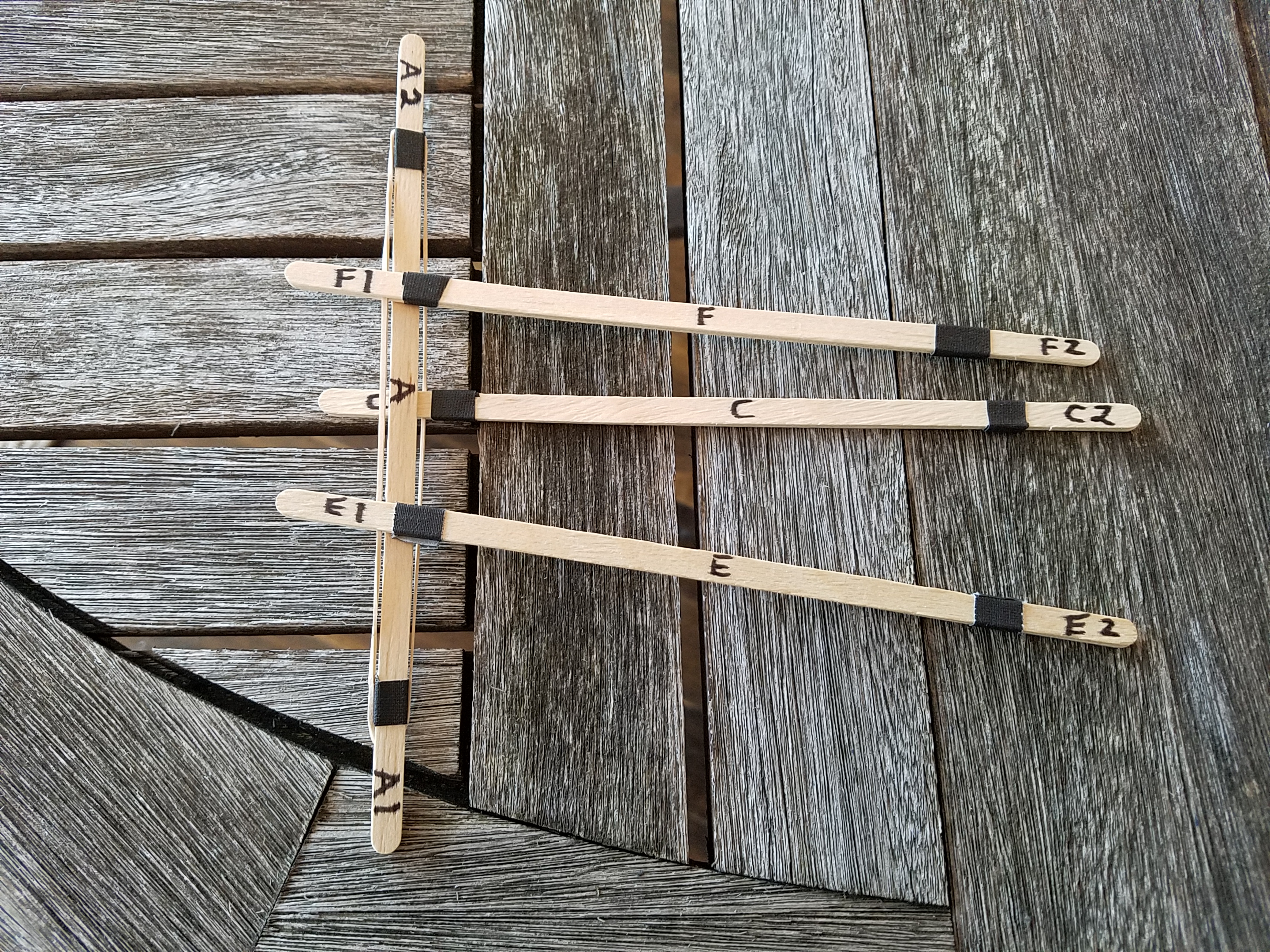
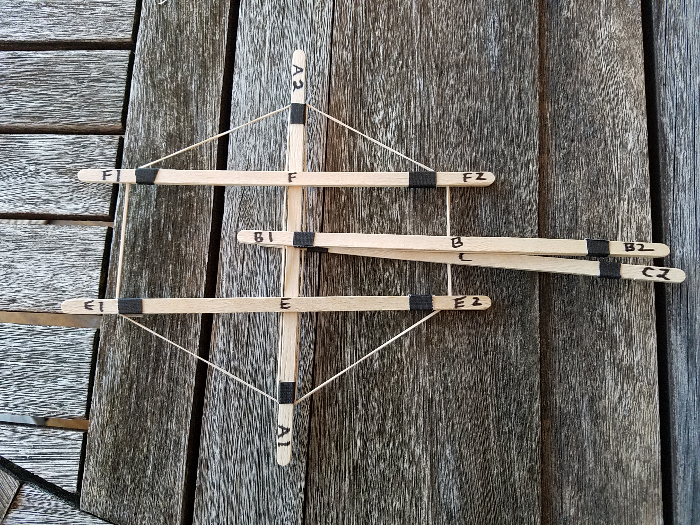
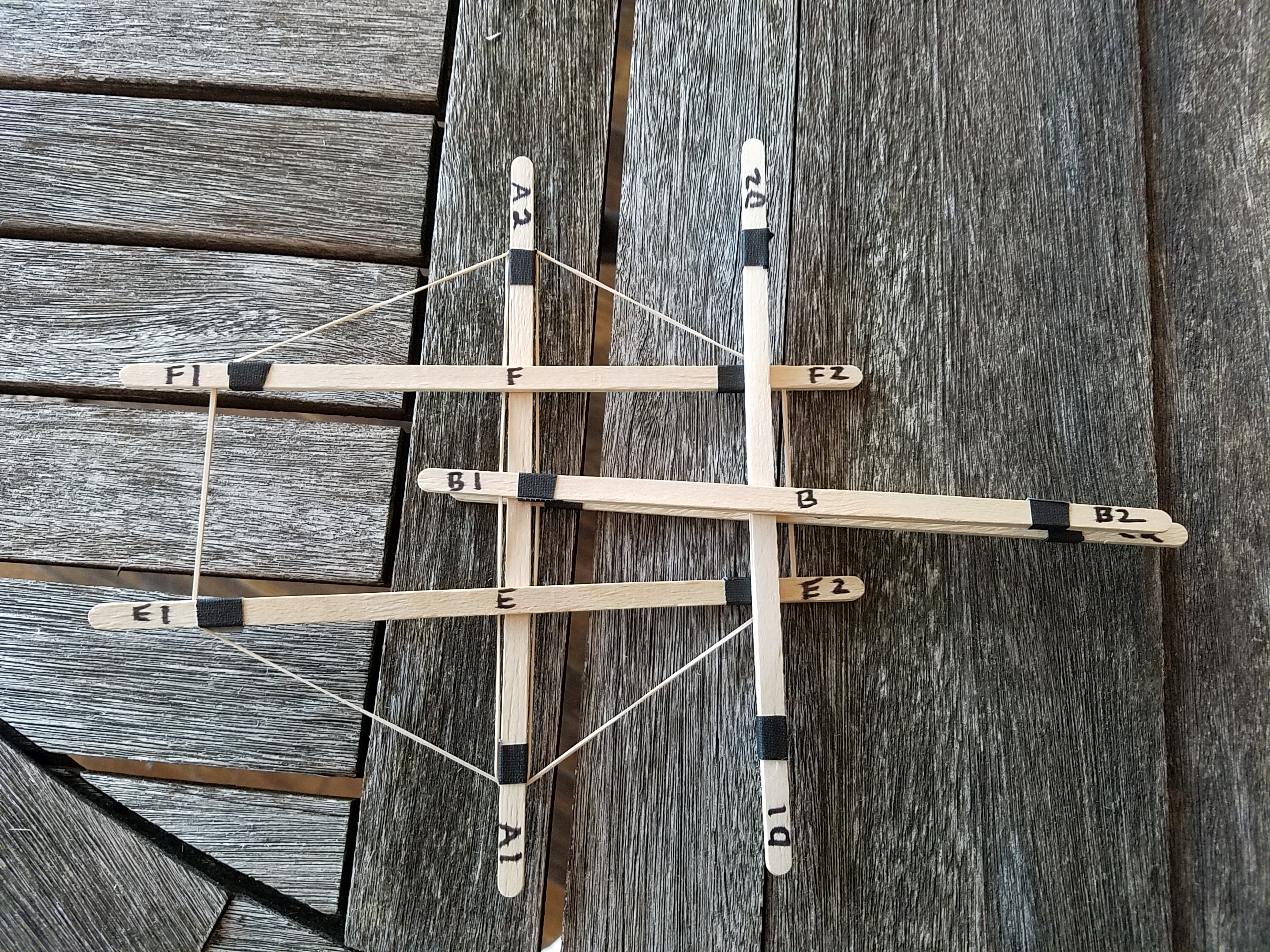
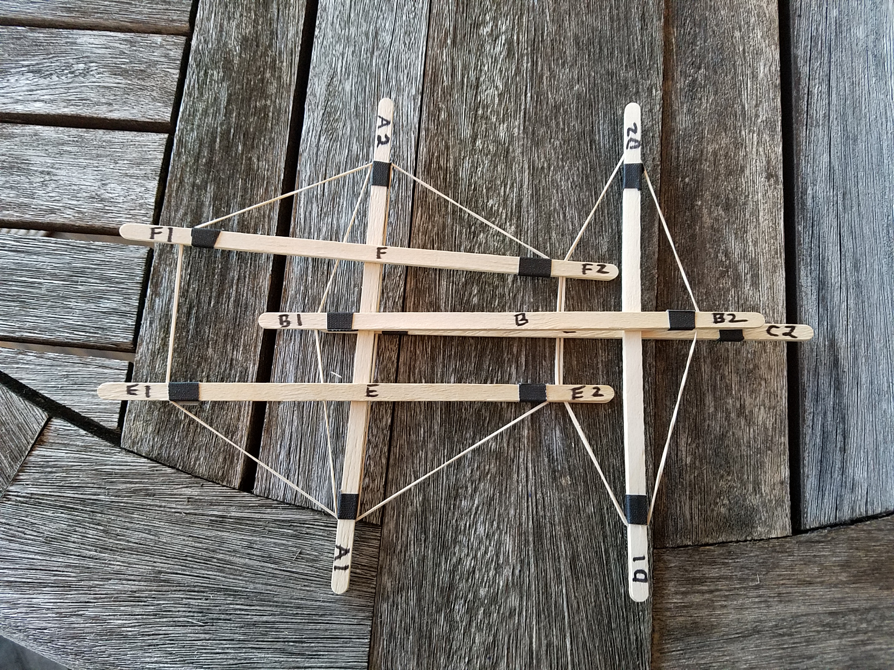
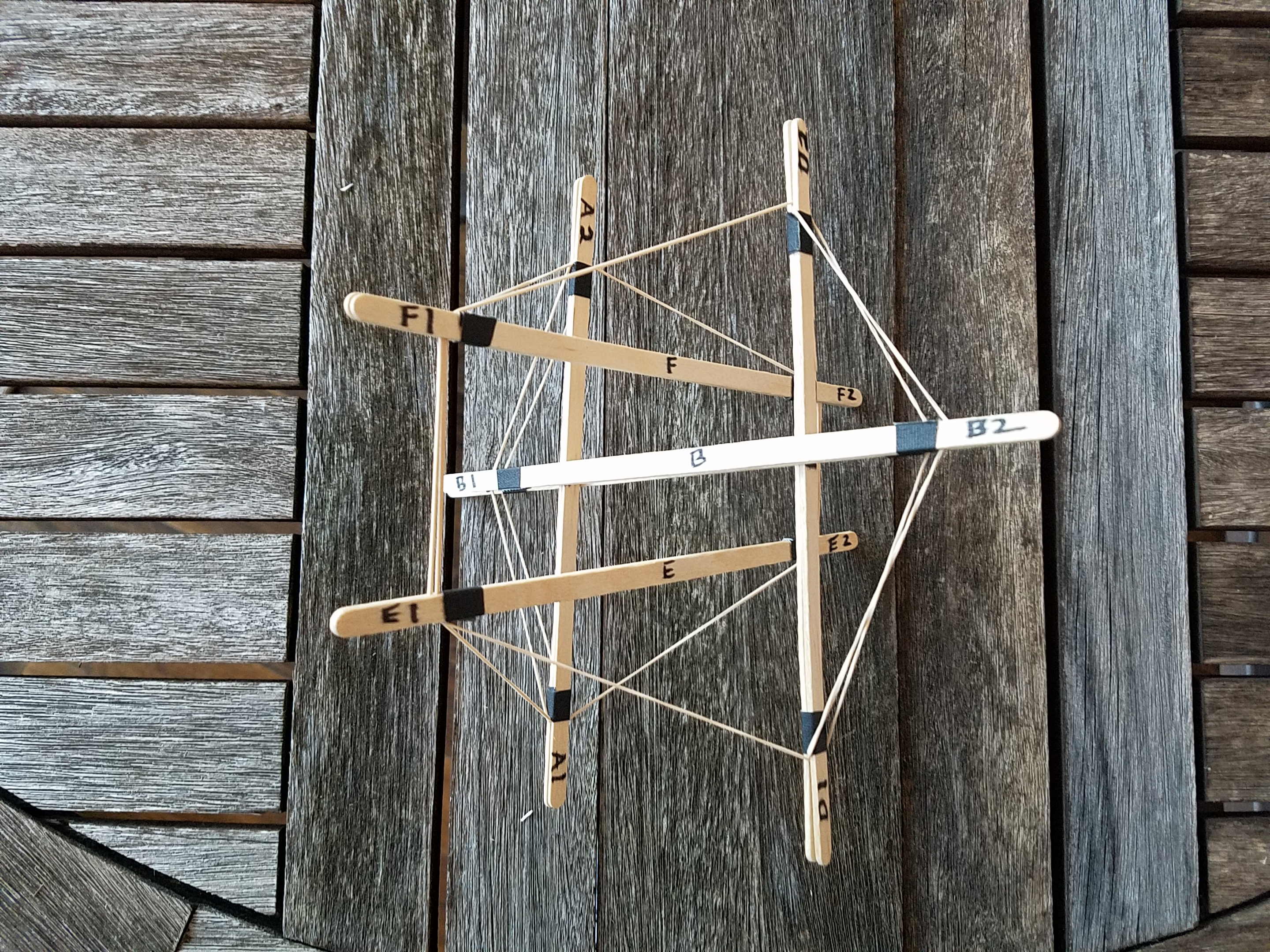
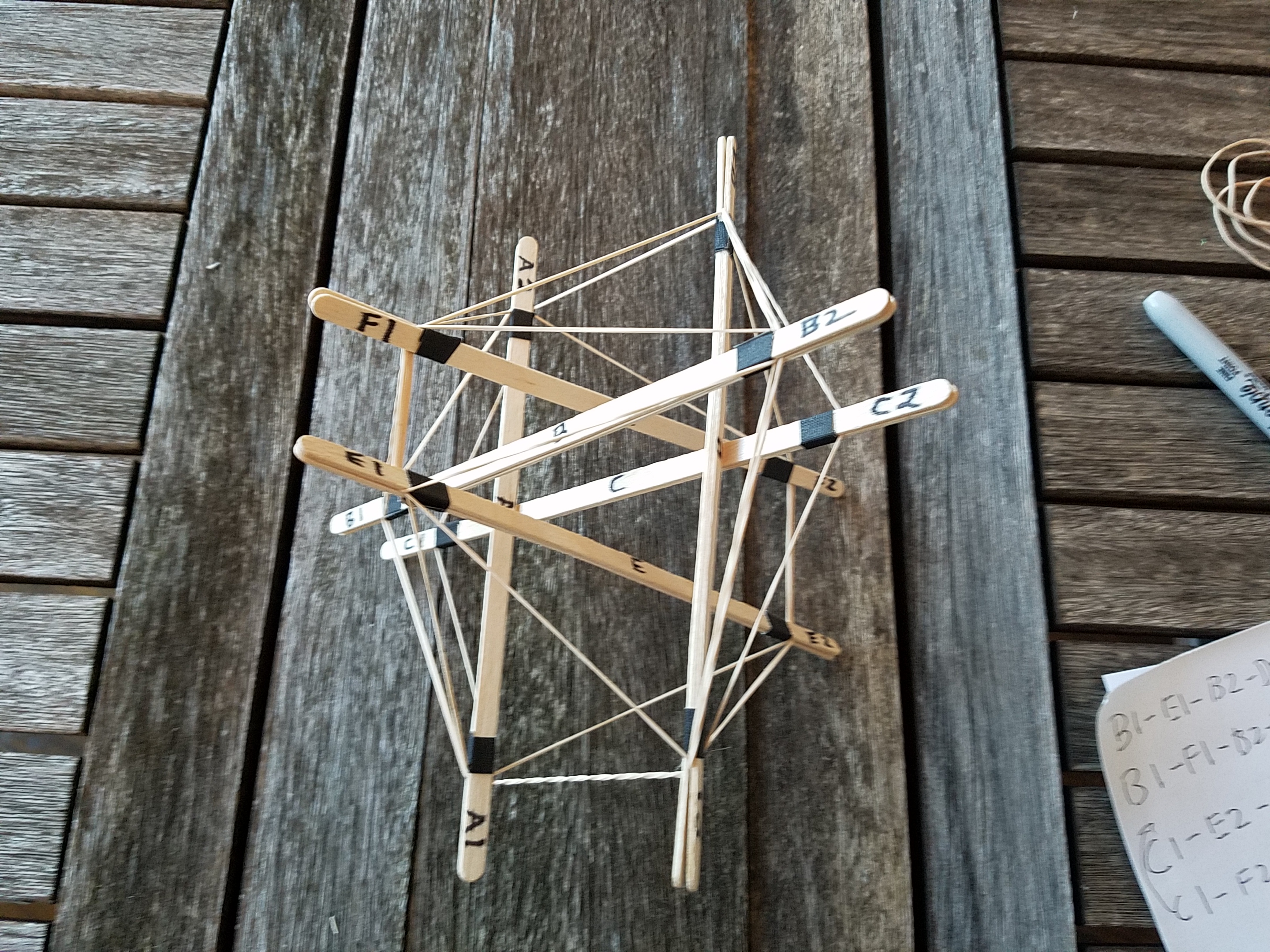
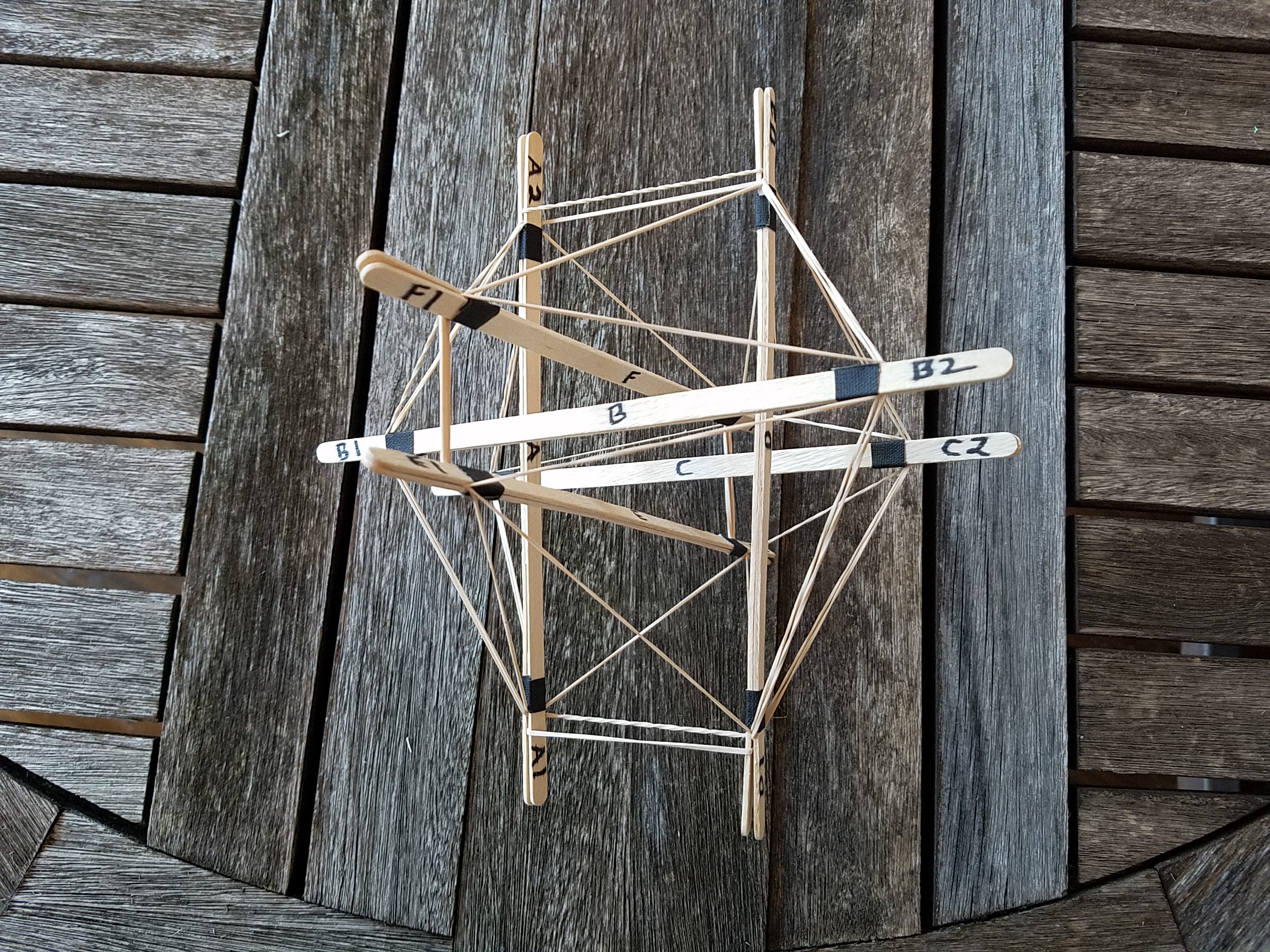
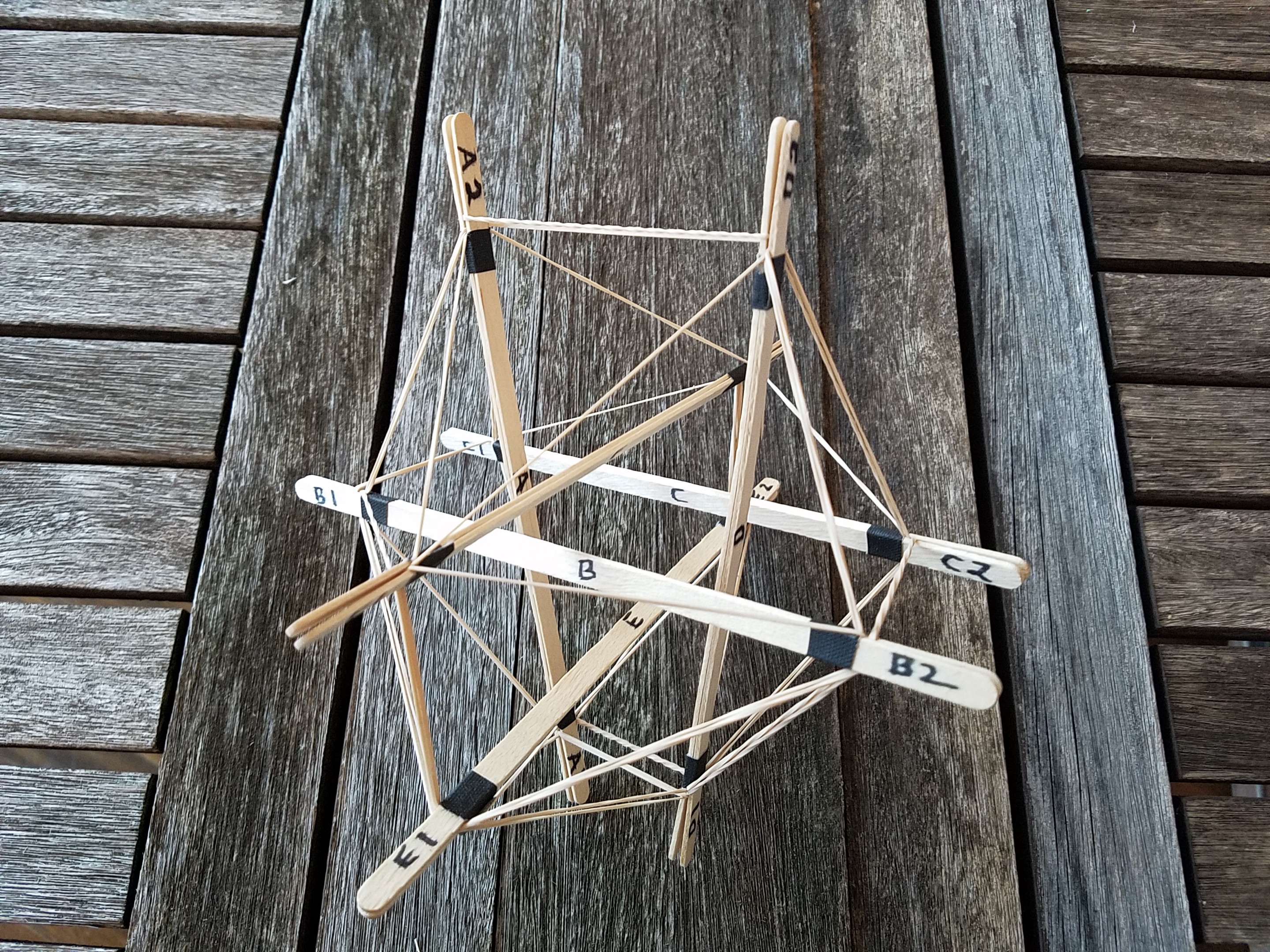
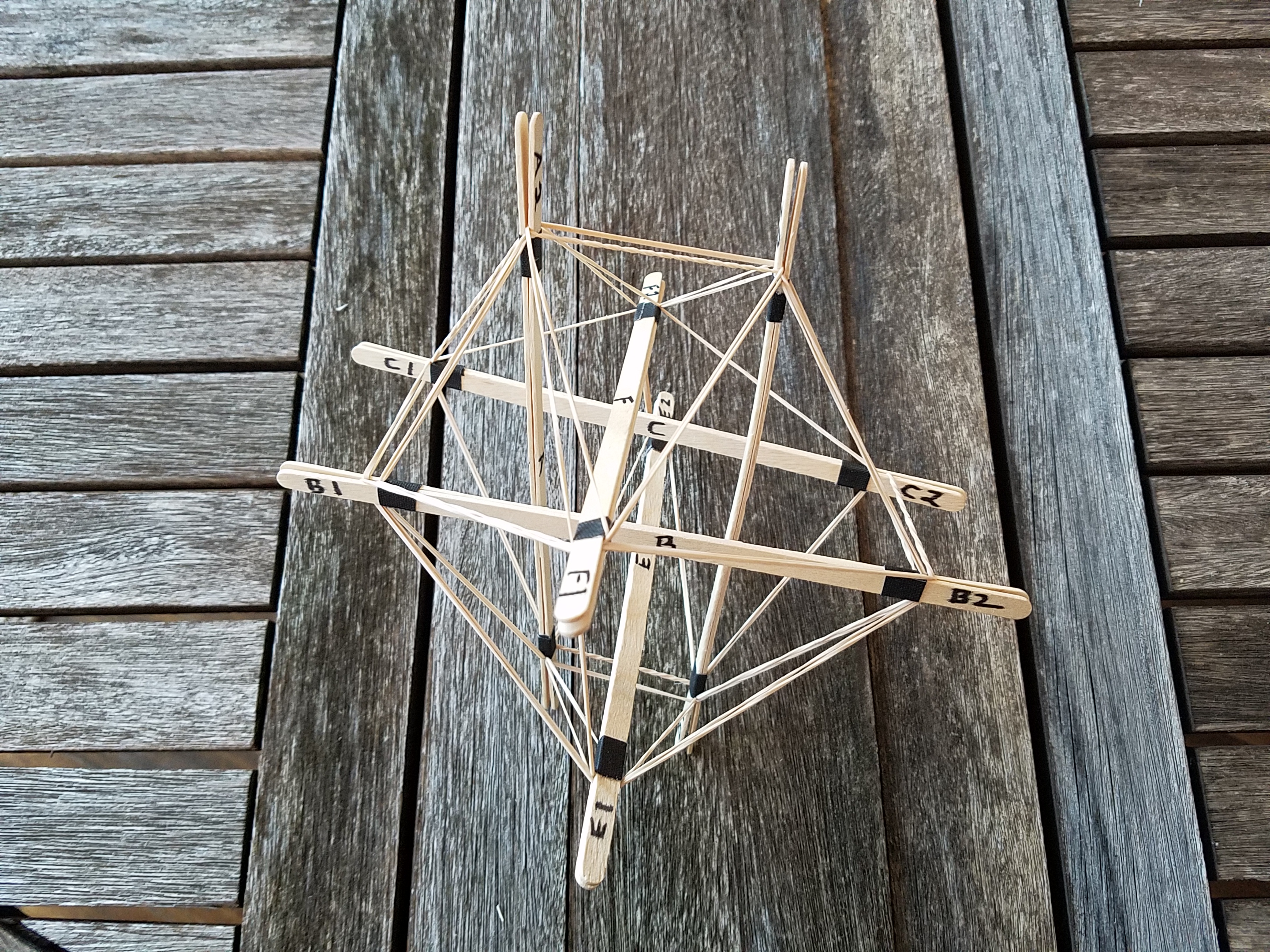
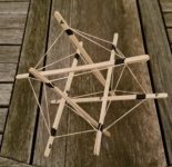
Actually note that only 10 of them need the cord, as no struts connect to the last five “expander” struts. Putting them together uses exactly the same procedure as with the small coffee-stirrer struts; here are a couple of intermediate snapshots.
       

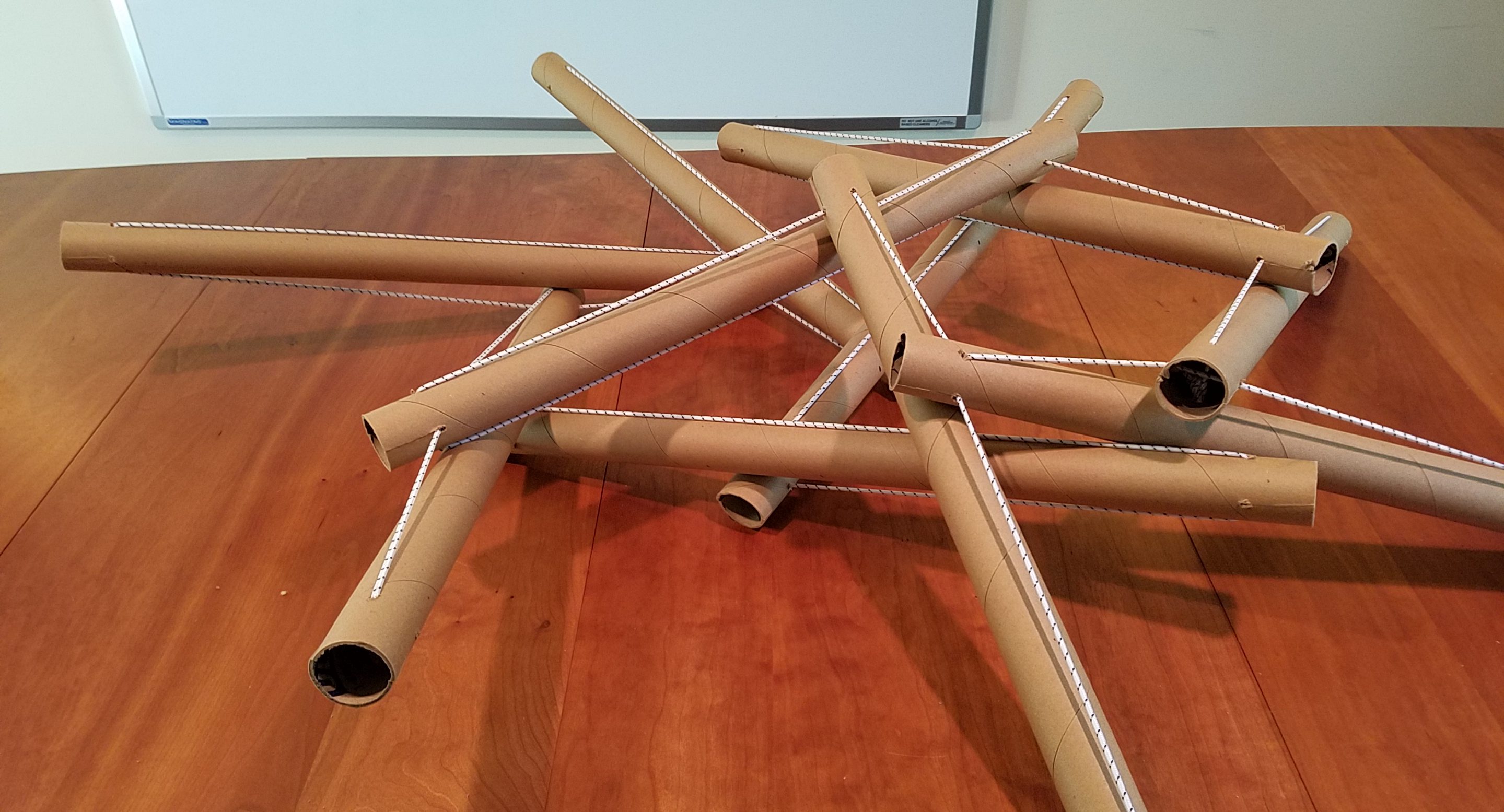
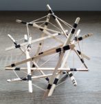
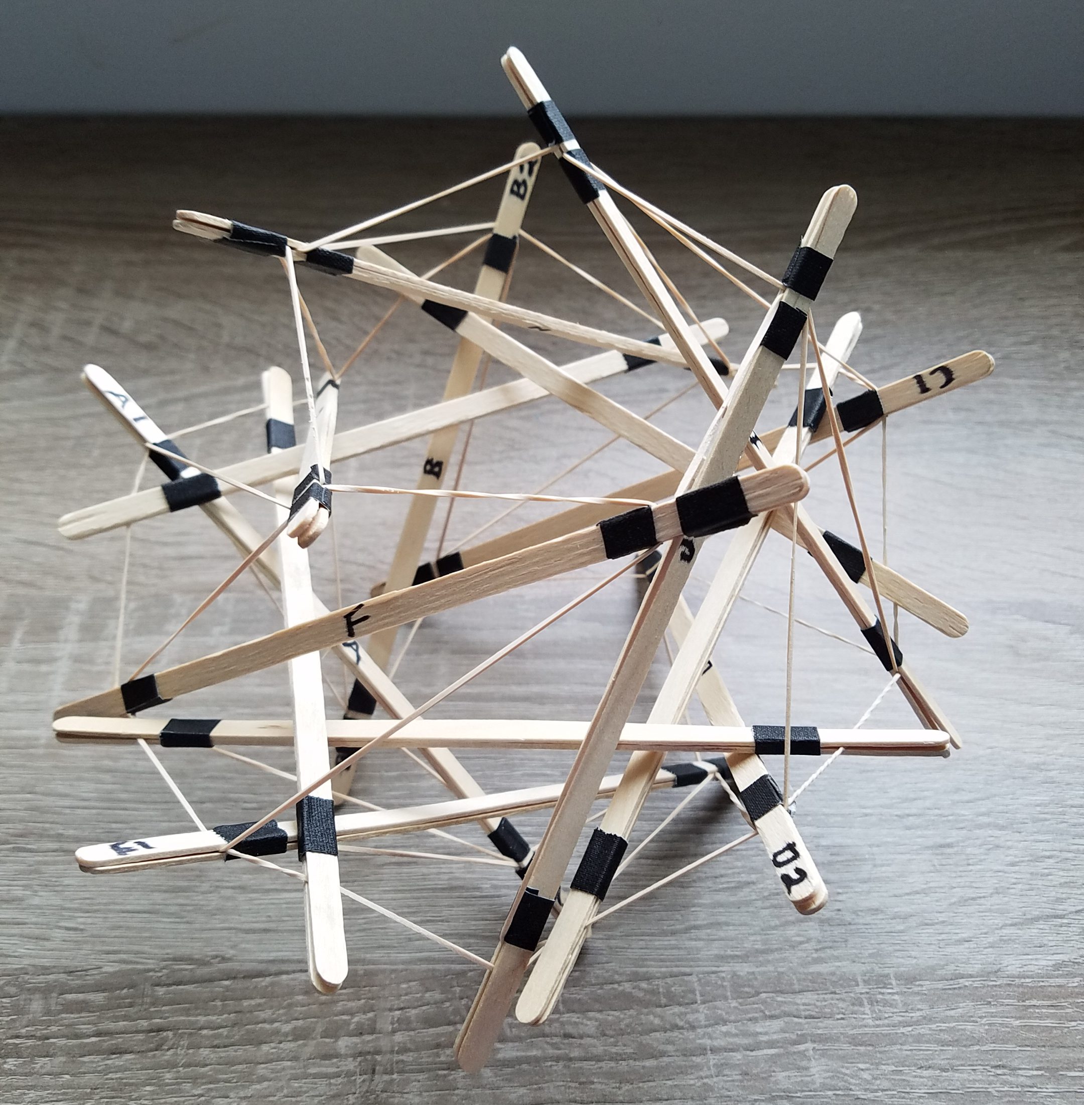
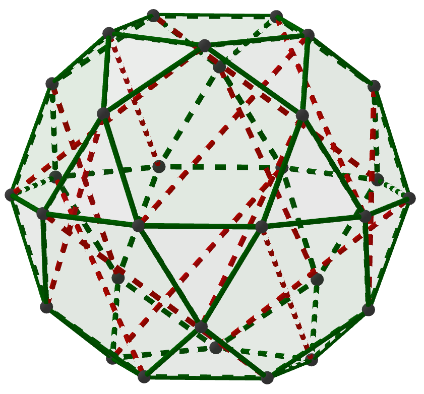
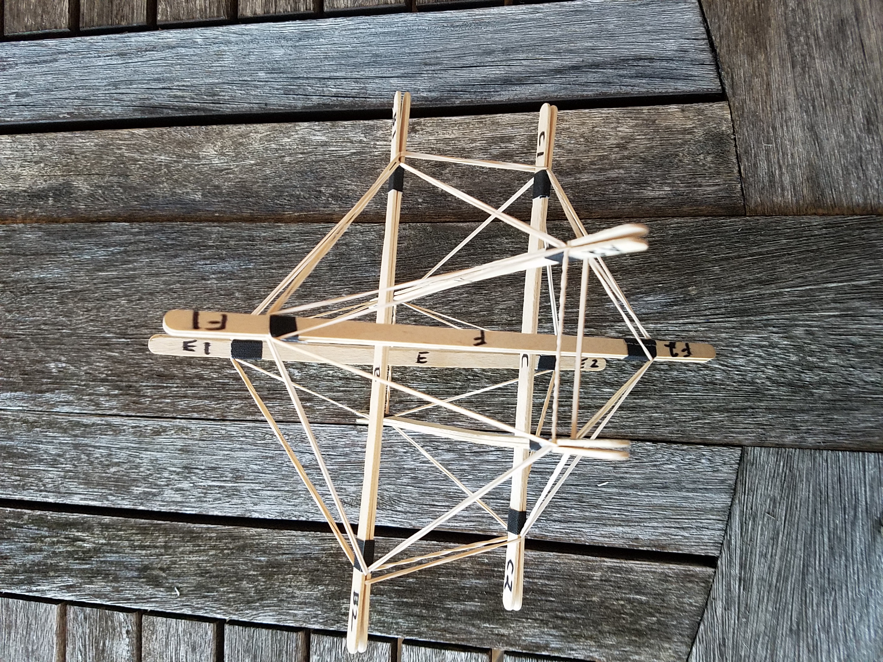
And here’s the final large-scale icloseidodecahedron:

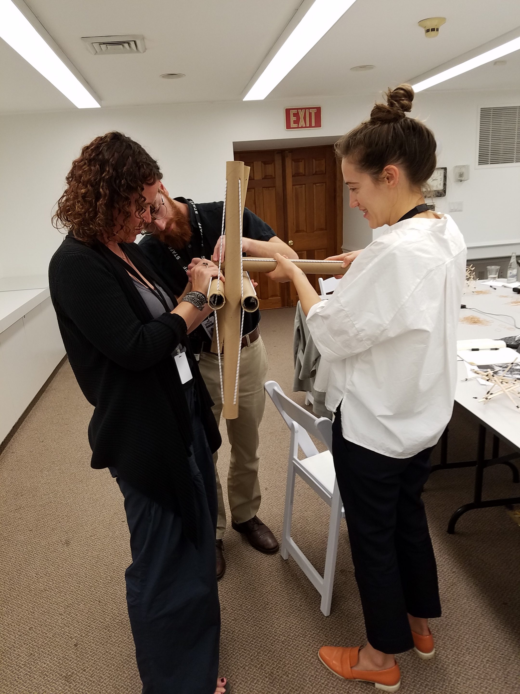
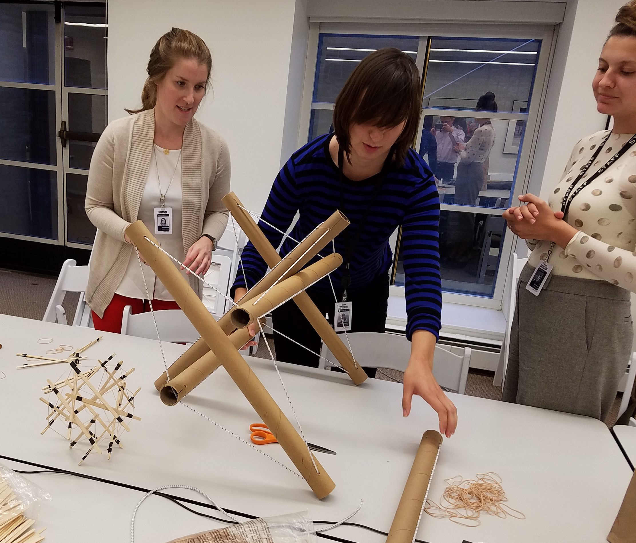
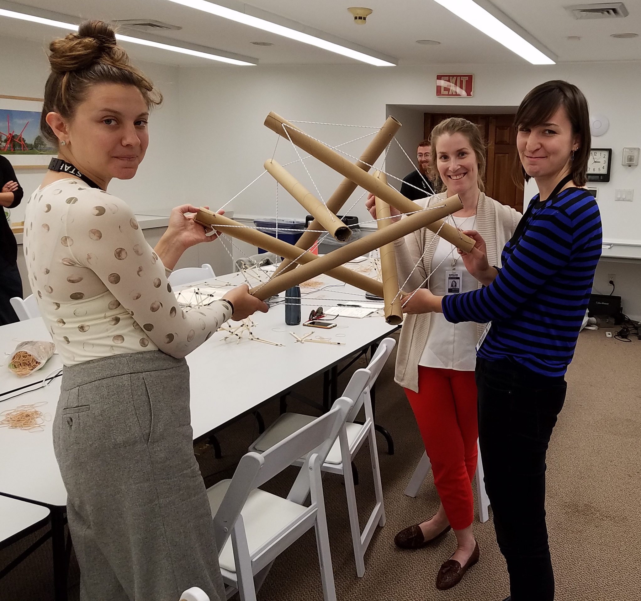
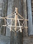
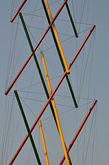
I’ll close out this series on tensegrity with some images of the staff at Storm King Art Center building their own large-scale six-strut tensegrity structures, and proudly displaying their results.


07 Nov

Good In Tensions

So why the interest in tensegrity here at Studio Infinity? It begins with Kenneth Snelson, the inventor of tensegrity (although perhaps not of the term) as a student of Buckminster Fuller. Ken went on to become a noted sculptor, using tensegrity in many of his works. One of those sculptures, Free Ride Home, resides at Storm King Art Center. And recently, the education department at Storm King Art Center invited me to give a workshop there about tensegrity, how to make simple models of tensegrity, and how to share ideas about tensegrity with the public visiting the Center.

Materials
15 struts; recommend labeling 10 of them A through J
10 rubber bands

Thus, much of what you see here at S reflects the thinking that went into that workshop. In particular for the occasion, I wanted to demonstrate a new tensegrity structure, and talk about its design process, as a means of strengthening the connections between math and art. This article will take you through building a model of that new structure.

Once you have your materials collected, you’re going to start by constructing a pentagon from five of the struts equipped with rubber bands. This pentagon will end up forming the bottom of the finished structure.

To build the pentagon, start by connecting one end of strut B to the rubber band strut A, one third of the way from one end of A to the other. Lie the two struts down so that B connects under the right side of A and extends off to the right, as shown. Then take another strut C and connect it to the right-side band of B, one third of the way along B from where B connects to A. Continue in this same fashion, connecting a fourth strut D to C in a similar spot, and a fifth strut E to D. At this point, what you have should look like this.

Now you can see that one free end of A is just in position to connect to E in the same way as all the others. So make that connection, and your pentagon is complete:

Now it’s time to make the top of the tensegrity structure, which is also a pentagon. This step gave me a great deal of trouble; I could make the pentagon just fine, but then the two pieces wouldn’t connect properly together. I struggled until the realization finally came that the top pentagon needs to be the mirror image of the bottom pentagon. So you need to reverse the earlier instructions.
           
Start by connecting one end of a strut G to the band of F one-third of the way from the end. Lay it down so that I connects to the left-hand side of F and extends off to the left. Now proceed to the left, connecting strut H to G, I to H, and J to I. Finally, strut J will connect back to F, producing the top pentagon which will look like this:

To continue the assembly, flip the top pentagon over and lay it on top of the first pentagon with the long ends of its struts lying between adjacent pairs of struts from the bottom. Now you’re going to “sew up” the two halves by connecting the ten free ends of the struts around in a circle. I will assume you’ve laid the top one down so that the strut labeled F lies between A and E on the bottom. Supposing so, you can start by connecting the free end of F to the rubber band of A. Connect it to the opposite side of A as the existing connection to A, and one-third of the way from the opposite end of A, as shown on the left.

Now just proceed around the circle, making connections in exactly the same way: the free end of G into B, the free end of H into C, I into D, and J into E.

Now you have to go back and connect the free ends of the other set of five struts. The free end of A is supposed to connect to G in exactly the same way as the previous five connections connections: on the opposite side and opposite end as the connection of H into G. It may seem ridiculous at first glance that the free end of A can get all the way over to where G now is, but just wrangle things around until it does. Then you “just” need to continue in the same fashion, connecting B into H, C into I, D into J, and finally E into F.

Unfortunately, the construction can get a bit tangled up as you go, as shown in the picture on the right, and you may find that some of the original connections are popping out. If you do, don’t despair; go back to the original pentagons and seal in the connections with additional pieces of tape on the other side of the rubber bands, as shown on the left. Then re-start the sewing process. In fact, the only reason not to simply take the precaution and secure the original connections as shown is if you think you may want to take your tensegrity structure apart again (and perhaps build something else).

In any case, if you persevere, you will eventually get to the last connection, of E back into F. To the right is a picture of what the structure should look like just before that last connection. Once the two halves are all sewn up, your structure should look like the following.

Now in theory, theory and practice are the same; but in practice, they differ, and here’s the point of divergence in this project. The theoretical plans for this construction called for a strut to extend between pairs of points as marked in red in the picture below (two of five such pairs are marked).

However, at this point I could see that the assembly already had most of the structure that I intended it to have; it was just taller and narrower than the intended icosidodecahedron. So most of what I wanted to accomplish was to spread out the middle of the nascent sculpture, so it would take on more of the desired ball-like form. And I wanted to do this in a way that would preserve the five-fold rotational symmetry that the structure so far possessed. So I shifted the new struts more toward the equator so that they would spread the structure more effectively, and planned them out so they would form roughly a pentagon.

So, to finish off the piece, take a new strut with no rubber band of its own, and connect it between the points marked in blue above. (You’ll notice the middle of the structure start to widen out a bit.) Note that there is a zig-zag band of ten short rubber segments (see the image to the right) around the “equator” of the structure, and you just have to connect the midpoints of two of those that are separated by two intermediate segments. The image at the left shows the structure with one such “expander” strut in place. The endpoints of the next expander strut will each be two of the zig-zag segments of that equatorial band away from the endpoints of the first, so that the two endpoints of the second strut are also separated by two segments. Continue adding the remaining three struts, proceeding two segments counterclockwise each time. You’ll find that none of the expanders interfere with each other, and each segment of the zig-zag band will receive exactly one connection. When all five of the expanders are in place, you’re done, and the finished tensegrity, dubbed the “icloseidodecahedron,” should look like this.
If you look closely, you can see the pentagon of unmarked struts in the middle of the above image. It may not be exactly an icosidodecahedron, but it’s not far off, and the resulting structure has pleasing five-fold symmetry, with a pleasant but not excessive complexity.

07 Nov

The icloseidodecahedron

When I set the goal of creating a new tensegrity structure for the Storm King Art Center workshop, I decided that I wanted to create a highly regular, symmetric structure, to contrast with the more free-form, organic style of Snelson’s Free Ride Home at the Center. (Snelson also created many very regular tensegrity sculptures himself.)

As is often the case, the creative process began with an existing structure that shared many of the characteristics I wanted, namely the classic six-strut tensegrity structure. In a previous article, we saw how that structure is based on a regular icosahedron; in fact, the compression members are just six diagonals of an icosahedron that are equivalent under the symmetries of the icosahedron. Moreover, the end points of the diagonals exhaust the twelve vertices of the icosahedron.

Thus, it seemed that I might obtain a different interesting structure if I started with a different polyhedron that shared some key properties with the icosahedron, and then looked for an appropriate set of diagonals. So the first question was, what are those key properties of the icosahedron? Well, we want all of the edges of the shape to be the “same” in some sense so that when we fabricate them from tension members with the same tension, they will balance each other uniformly. And what does “same” mean in this context? Well, a natural answer is that there should be some symmetry of the shape — in other words, some shape-preserving transformation, which in this case will be a rotation — which will match any edge up with any other edge. When the symmetries of an object completely scramble some component of that object, mathematicians call the object “transitive” for that component. So I could find a list of candidate shapes by an internet search for “edge-transitive polyhedron.” That search turned up a fancy synonym for edge-transitive, namely “isotoxal,” and it also turned up this Wikipedia page, of which the first table is of particular interest.

The rhombic triacontahedron immediately caught my eye. However, it includes two different categories of vertices, the ones where five edges meet and the ones where three edges meet; and what’s worse, there are twelve of the former but twenty of the latter. That means there will be no way to make sixteen equivalent diagonals, since some of them will not terminate at a five-edge vertex at either end, while others will.

So instead, I set my sights on it’s left-hand neighbor in that table, the icosidodecahedron. It has 30 identical vertices (consistent with our theme, the symmetries of the icosidodecahedron act transitively on the vertices). So then I searched for a set of fifteen diagonals of the icosidodecahedron, all the same length, to be the struts of the new tensegrity.

I began with what seemed like the simplest sort of diagonal, namely a diagonal between two vertices that are only “two edges apart,” i.e., both adjacent to the same vertex. I was able to draw a set of diagonals that exhausted the vertices, like this:

However, there’s a problem: you can see on the right-hand side of the image that two of the diagonals selected intersect. While that’s OK mathematically, there’s no way to direct struts to pass through each other. And try as I might, I couldn’t avoid two of these diagonals intersecting. From a math point of view, the natural response was to try to prove that any such set of diagonals contains (at least) two that intersect each other. That turns out to be the case, and here’s how the proof goes: Any diagonal that connects two vertices that are adjacent to the same vertex is actually a diagonal of one of the pentagonal faces of the icosidodecahedron. There are only twelve such faces, but we need 15 diagonals. Hence, at least one of the faces will end up with two diagonals. And (as you can demonstrate for yourself by drawing some diagrams) any two diagonals of a regular pentagon intersect.

So these “simplest” diagonals were out. And it also occurred to me that for building a tensegrity structure, we likely want long diagonals that go through the body of the polyhedron, to make it easier for the tension of the rubber bands along the edges of the polyhedron to pull against them. The very longest diagonals of the icosidodecahedron all intersect each other at the center of the polyhedron, so they’re out. Therefore, my next attempt was to use the second-longest diagonals, like this partial effort:

You can see that this selection of diagonals already has intersecting pairs. In fact, I was not able to find any selection of diagonals that fit the requirements above, leading to this Math StackExchange question. So what did I do? I settled for the “near miss” below. The ten diagonals that connect a “polar” vertex to an “equatorial” vertex are transitive, but there’s no way to transform them to one of the other five diagonals (that connect two “mid-latitude” vertices, one above the equator and one below.) In fact, the two types of diagonals are different lengths, with the first type about 20% longer than the second. So I couldn’t expect the resulting tensegrity structure to come out regular, using struts the same length for diagonals that should theoretically be the same length. But I hoped it would at least be close.

So this image became the template for building the new tensegrity structure, which you can read about in the next MakeStream post.

07 Nov

The elusive iforceahedron

OK, so now we are going to try to force a tensegrity structure to take on the shape of a truly regular icosahedron. But we don’t have to search blindly for a way; we are armed with the results of this MathStream post about how to do it. To sum those results up, if we label the ends of the struts as shown in this diagram, then we need to place twelve rubber bands along the following paths: A1-C1-A2-F1-E1  A1-B1-A2-F2-E2  D1-B2-D2-F2-E2  D1-C2-D2-F1-E1  B1-E1-B2-D2-A2  B1-F1-B2-D1-A1  C1-F2-C2-D1-A1  C1-E2-C2-D2-A2  E1-A1-E2-C2-B2  E1-D1-E2-C1-B1  F1-D2-F2-C1-B1 and F1-A2-F2-C2-B2.

Materials
6 labeled struts
12 rubber bands

These building directions are not as intuitive as the ones for the original not-quite-icosahedron, so I strongly recommend that you take your six struts and label the ends clearly before you start to build anything.

The first rubber band is easy: just take the ends of the struts named and space them out equally along the band, as shown below. Note this means that you need to leave more space on one side of strut A than the other, because there is only one connection between A1 and A2 on one side (namely C1) but two connections on the other side (F1 and E1).

The second rubber band is trickier: you have to make sure to leave the shorter segment of the band on the opposite side of strut A as last time, and stretch the longer segment around to connect to the far end of the E and F struts.

Before inserting the third or fourth rubber bands, it’s helpful to place the D strut among the others in roughly the position it will end up.

Here it is with the third rubber band (which really doesn’t yet want to stay in place).

And here it is after four rubber bands, which makes everything much more snug and gives the nascent structure much more shape.

At this point, it becomes much easier to simply wrap each rubber band around the five points it is supposed to connect, trying to keep an even amount of tension on the rubber as you go. Here’s the structure after two more rubber bands (the two that each intersect both ends of the B strut) — we’re half done!

The following two pictures show the state after eight and ten rubber bands, respectively.


And here we are upon first getting all twelve rubber bands in place. It doesn’t look regular yet, but maybe it just needs tweaking the rubber bands to make it symmetrical.

However, here we are after quite some time spent pulling rubber into the segments between the ends of parallel struts, to try to lengthen those segments and shorten the other segments. At this point, the rubber bands are getting pretty loose between the parallel struts, and taut to seem near the point of breaking on the other segments.

So we reach the inescapable conclusion that you can’t force a tensegrity structure on six struts like this to adopt the shape of a regular icosahedron. Is that a disappointing result? Quite the contrary; it’s always kind of exciting when things don’t work out the way you expect. It often means that something deeper is going on, waiting to be unraveled. And in retrospect, we had a clue from the original structure that this might not work out. Namely, you can observe in that structure that the ends of parallel struts are closer together than the ends of non-parallel struts, even though there are no direct rubber-band connections between these points. Intuitively, adding rubber connecting the ends of parallel struts can’t make them move any further apart, only bring them closer together. Hence, since we needed to spread those points apart to change the original tensegrity structure into a regular icosahedron, we were doomed to fail.

Thus, there remain mysteries in even the most familiar of tensegrity structures, that Studio Infinity will return to one day. Is there any way to create a truly regular icosahedron with tensegrity?

07 Nov

Balance of forces

As mentioned at the end of the last MathStream post, the actual shape that the six-strut tensegrity structure takes on is close to, but not quite precisely, a regular icosahedron. And that fact immediately makes you want to build a tensegrity structure that will under ideal circumstances assume the shape of a truly regular icosahedron. What would that entail? Why is the classic tensegrity not a regular icosahedron? One possibility that immediately comes to mind is that not all of the edges of the icosahedron are represented in the same physical way in the model. Namely, as you may recall from this diagram,there is no rubber band lying along some of the edges of the icosahedron. To test if that’s the reason that the six-strut is not regular, we’d want a different arrangement of elements so that there will be exactly the same tension on a rubber-band connection between every closest pair of endpoints of the six struts, as shown in this diagram.

So, you might immediately start tying to build such a configuration. But that will bounce you right back to a mathematical question: how can we route the rubber bands so that there is exactly the same amount of rubber band between every closest-neighbor pair of endpoints? In fact, one of the wonderful things that happens at Studio Infinity is that many of the things we try to build lead to new mathematical questions, and many of the mathematical discoveries we encounter suggest new things to build. So the MakeStream and MathStream really build on each other.

Getting back to the question at hand, it amounts to finding a route for each of several rubber bands so that the route of each band traverses the same number of edges of the icosahedron we are trying to achieve, and so that every edge is covered. Since the icosahedron has thirty edges, that immediately narrows down the possible number of rubber bands we might use. For example, there might be ten rubber bands each covering three edges, or six rubber bands each covering five edges, or five rubber bands each covering six edges, and so on. And since each rubber band is a loop, the edges covered will have to form a loop on the surface of the icosahedron. For example, there are fairly obvious loops one could make with three edges (in blue) or with five edges (in red) in this diagram.

So you can just start trying to cover the edges with loops of the same length. In fact, I recommend that you give it a try right now, maybe using the six-strut model you’ve made, or the diagram above. See if you can find a way to route rubber bands to cover every edge, so that every loop is the same length, before you read further.


After a while of trying, you may start to get discouraged. You might start to feel that this is an impossible task. And that would not be too surprising, because it is impossible. But when we make a statement like that in mathematics, we have to back it up. If you want to claim that something is impossible, you can’t just list the seventeen things you tried that didn’t work. You’ve got to find reasons why no possible routing of rubber bands, no matter how clever, will cover all of the edges and have every loop be the same length.

And the key to that in this case is even and odd. First count how many edges meet at every vertex: five, an odd number. Next count how many of those edges rubber bands can cover. Well, every rubber band is a loop, so it must arrive at the vertex by some edge, and then leave that vertex by a different edge. It might later come back to that vertex by yet another edge, but if so, it has to leave again by a still further edge, in order to form a single closed loop overall. So in short any one rubber band covers an even number of edges touching the vertex. And since the sum of a collection of even numbers is even, we can be sure that the rubber bands are covering an even number of edges touching the vertex.

And so now we run into the problem. An even number cannot be equal to an odd number, so we can’t possibly have covered all of the edges. So there in fact is no way to route the rubber bands as desired.

So we regretfully conclude that there is no way to construct the regular icosahedron we are looking for, right? Not quite. Another habit in mathematics is, when something doesn’t work out the way you thought it might, to see if there’s a way to change the assumptions so that it does work out. And in this case, there is something we can change: rather than providing the tension between two neighboring endpoints by virtue of a single segment of rubber band, why couldn’t there be exactly two different (but identical in length) segments of rubber band covering each edge? Then there would be ten different segments of rubber band reaching each vertex, which is an even number, and the contradiction underlying our impossibility argument would melt away in a puff of logic.

And now we can very pleasantly notice that there are exactly twelve of the five-edge pentagonal paths similar to the one highlighted in red in the last diagram above, and that each edge lies on exactly two of these pentagonal paths. So now the plan is simple: connect one rubber band along each pentagon, and the icosahedron should simply materialize from the balance of forces. Let’s return to the MakeStream to see if it works…

07 Nov

The icloseahedron

So maybe you’ve made the classic six-strut tensegrity (or perhaps you’ve just looked at the pictures) and you’re wondering what shape that is, exactly. Naturally, since mathematics is among other things the science of shape and structure, understanding that is going to involve a little math. And in mathematics, sometimes it’s easiest to understand something by breaking it down into the pieces that are there, but other times it’s actually easier to understand something by adding (or pretending to add) pieces that aren’t there.

So take a look again at the structure you built.

Notice that in many cases, two neighboring endpoints of struts are connected by segments of rubber band. However, in other cases, there are endpoints of two struts that are close together but are not connected at all. So let’s imagine what the structure would look like if all of the nearest neighbors were connected.

Now, if we look at the outer surface of the structure, we see a much simpler pattern. Every outermost flat shape of the structure — which we call a face of the structure — is a triangle. There are 20 of these triangles, and at each endpoint of a strut, which makes a sort of “corner” of the structure called a vertex, exactly five of the triangles meet. There’s just one geometric shape fitting those facts, called the icosahedron.

This shape is simple and natural enough to have been discovered at least two and a half millennia ago, as one of the five Platonic Solids of the ancient Greeks. These are the shapes with identical regular polygonal faces and identical vertices, and it is a remarkable and beautiful fact that only five different Platonic solids exist. Yet the icosahedron is also intriguing and pleasing enough that it’s still of interest today.

One of the most important characteristics of the icosahedron is that it has very many symmetries. A symmetry of an object is some transformation, like a rotation or a translation or some combination thereof, which brings the shape back to coincide with itself. For example, if we were to rotate the icosahedron one-fifth of a turn around the axis indicated by the dotted blue line in this diagram, it would again look exactly the same, even though we moved it.

In the idealized world of this Platonic icosahedron, how can we represent the struts? Each one of them connects two of the vertices of the icosahedron, so it is what you might call a diagonal of the icosahedron. Let’s draw all six of them on our diagram.

Note how these diagonals are arranged; each one connects a vertex to another vertex that’s not adjacent, but lies “two edges away” from the starting vertex. They come in three pairs of parallel diagonals. Moreover, all six diagonals are “equivalent” under the symmetries of the icosahedron, which means to say that there’s a symmetry of the icosahedron which moves any of the struts to the position of any one of the other struts. That corresponds with the fact that all of our struts are the same length: in order to get an icosahedron, it’s necessary to use struts that are the same length, because there’s no way to tell one strut from another. They’re all interchangeable by the symmetries of the icosahedron.

We’ll close this tour of the math underlying the six-strut tensegrity with a perhaps inconvenient-seeming observation. If you look closely at the structure you’ve built (or at the pictures above), you will see that the icosahedron is not actually perfectly regular. In the diagram, the dotted sides of the triangles are not the same lengths as the rubber-band sides of the triangles. So our tensegrity structure is not actually a Platonic regular icosahedron; you might instead dub it an “icloseahedron” since it’s really close to, but not quite identical to, the idealized structure we envisioned.

But why isn’t this structure regular? After all, we built it in a very symmetric way. Well, there’s one way in which the physical structure of the six-strut tensegrity differs markedly from a true icosahedron — and we’ll take that up in the next MathStream article.

HERE!! go on about symmetries, show how the struts relate, point out that the tensegrity isn’t precisely a regular icosahedron, end with wondering why, saying that will have to wait for another post.

07 Nov

The Nitty (Tense)Grity

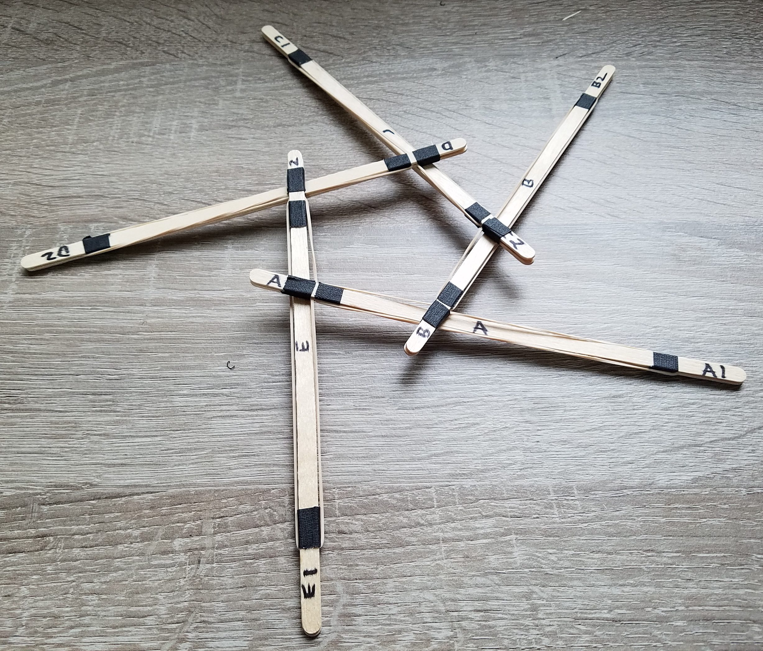
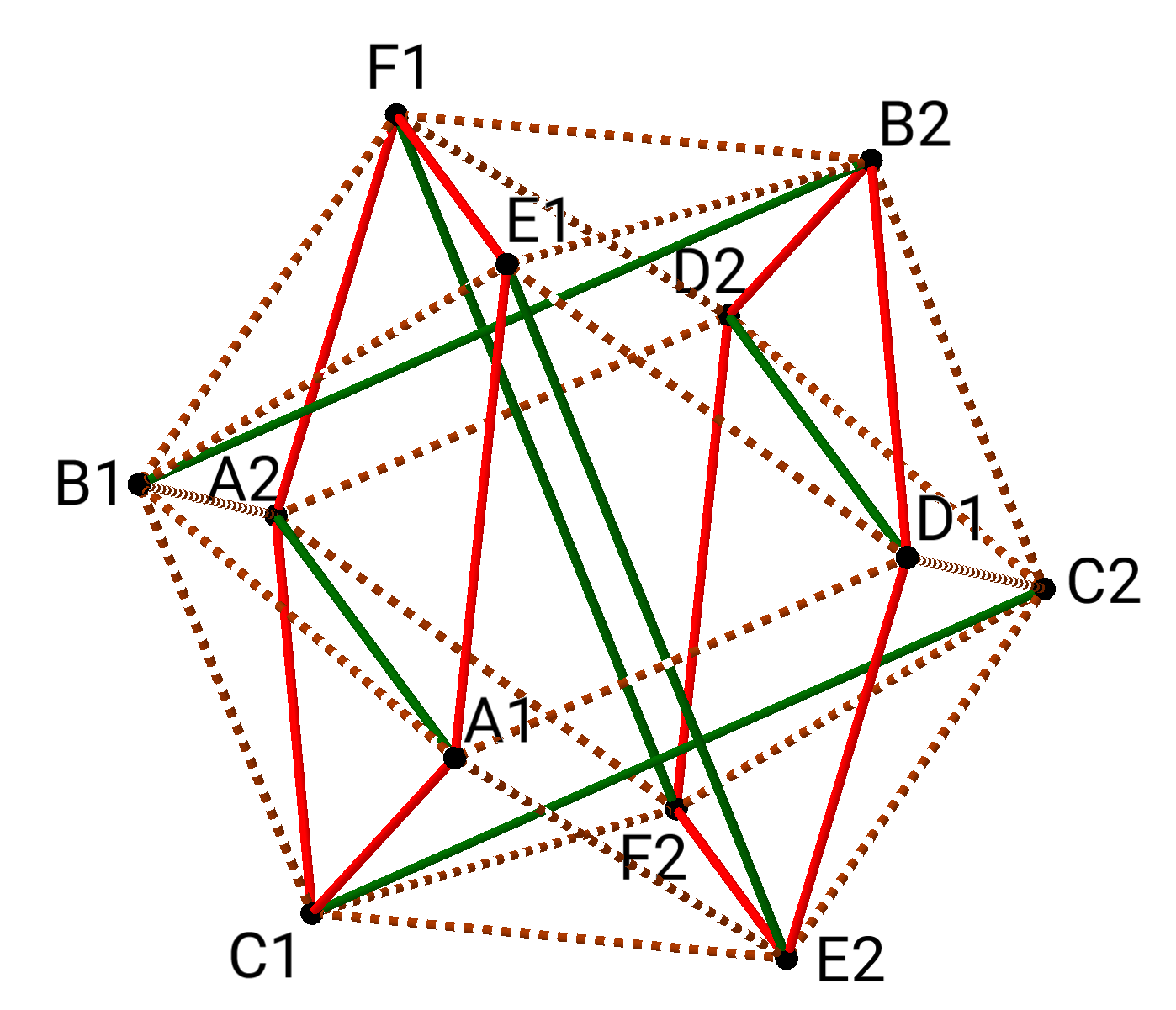
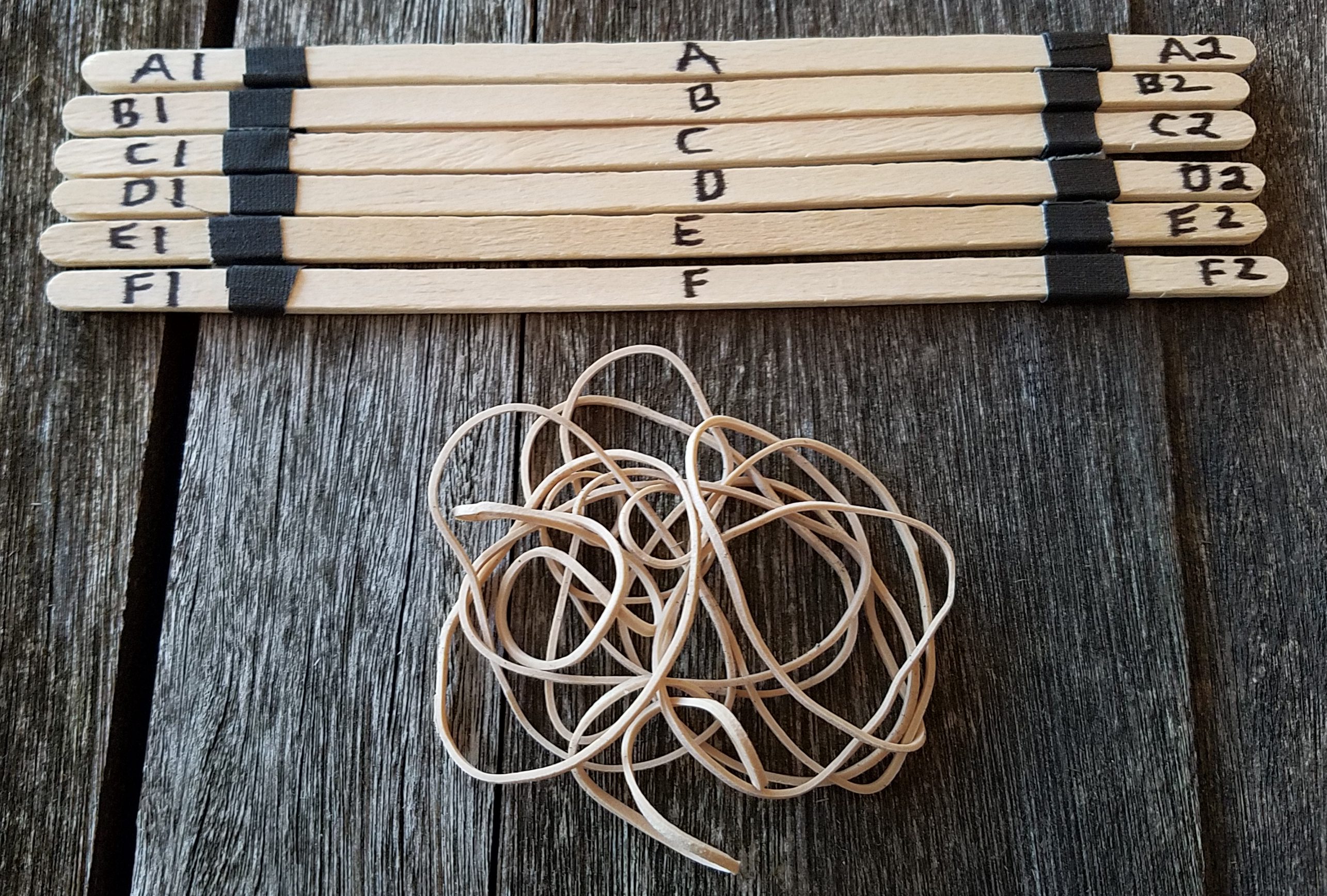
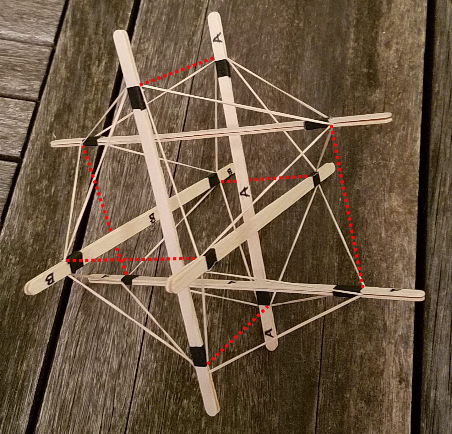
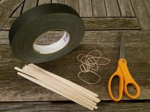
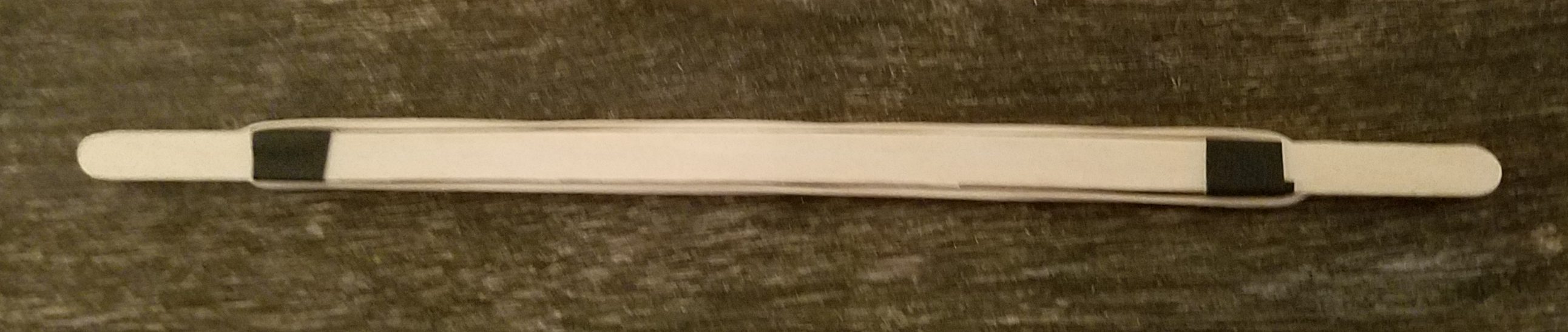
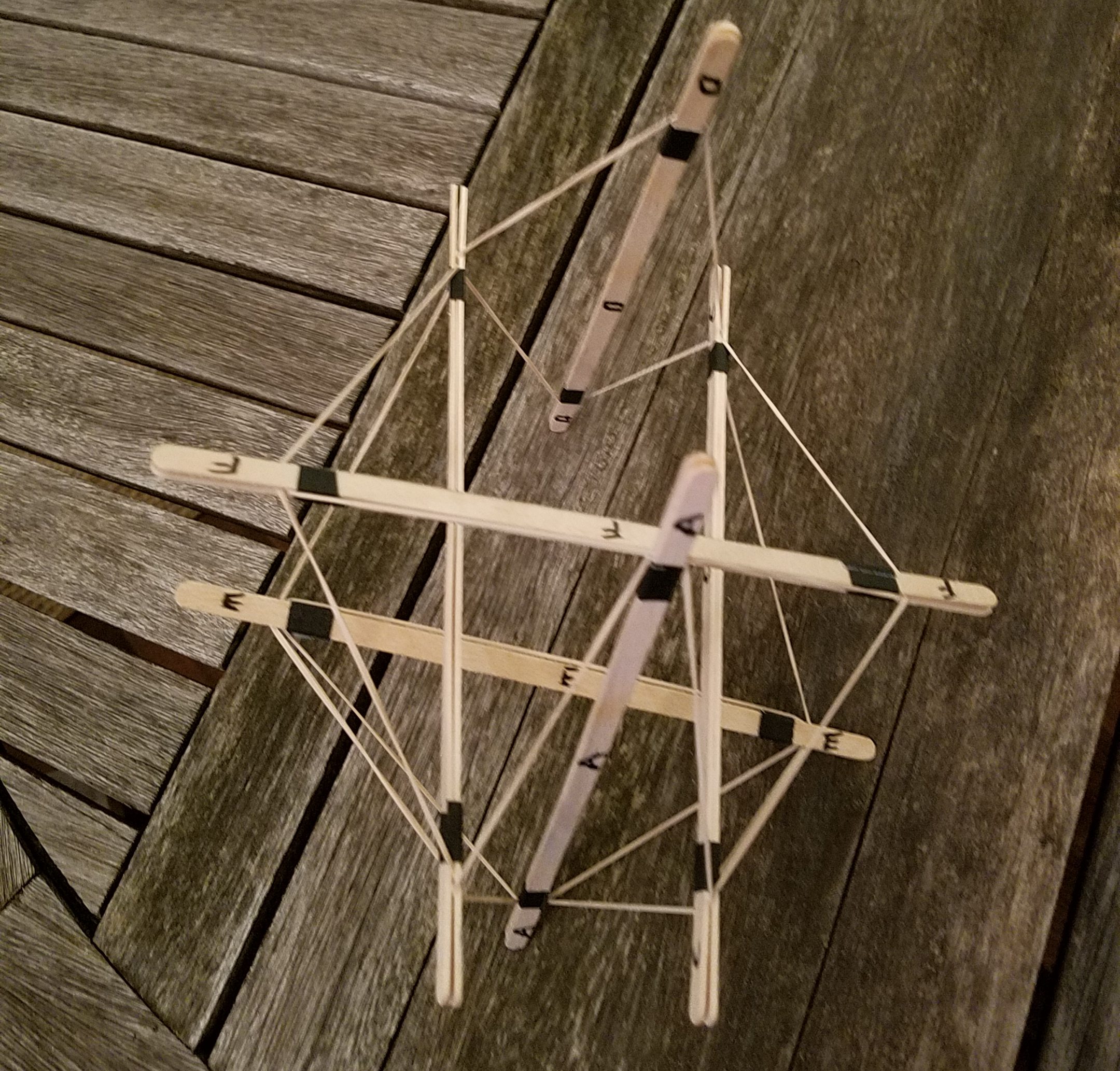
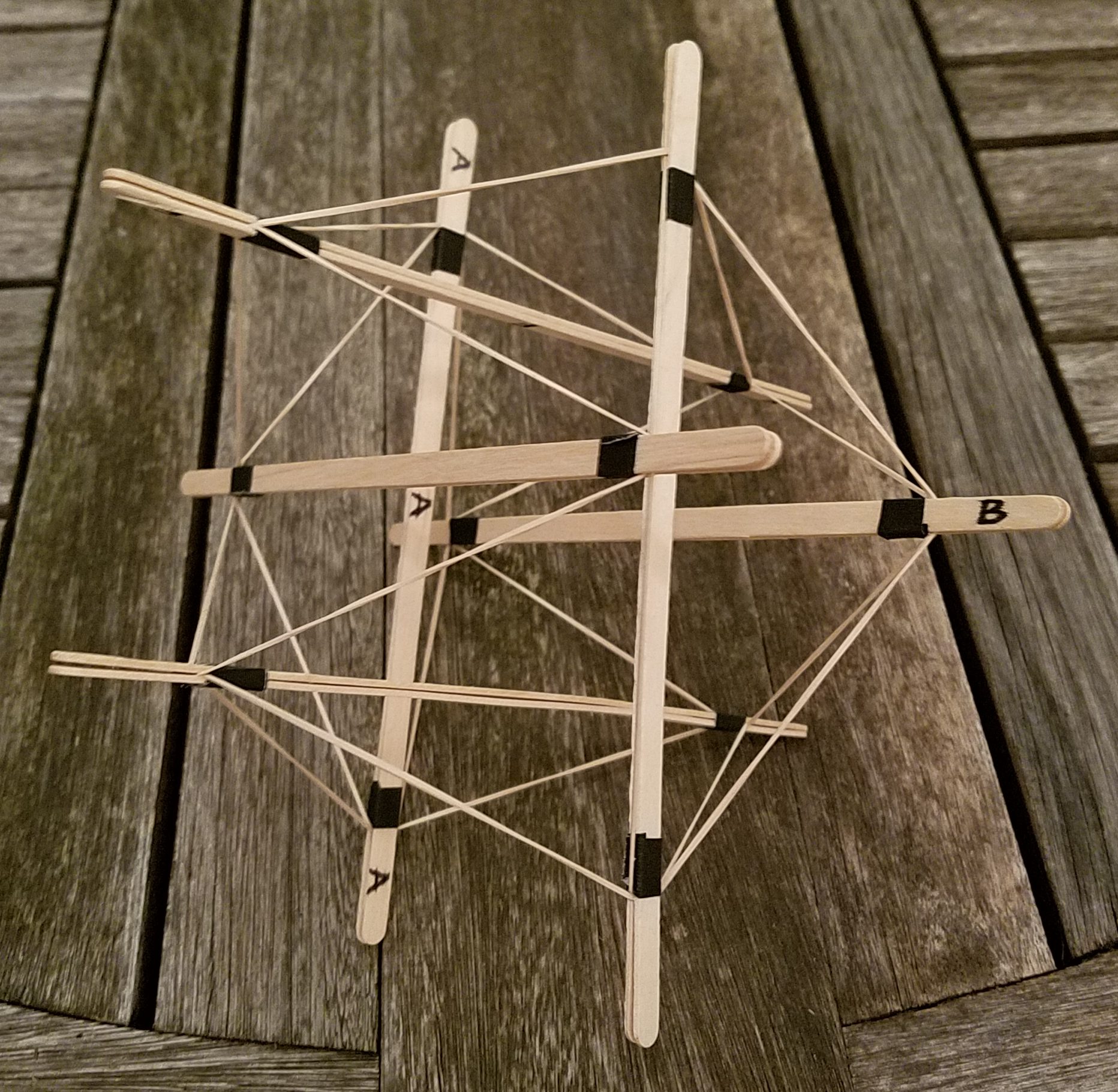
Studio Infinity is kicking off with a group of articles that feature the concept of tensegrity. What does that mean? A three-dimensional structure displays tensegrity if its compression members — rigid components that can hold their shape even when pushed inward by external forces — are connected only by tension members — materials that become taut when pulled outward, but which deform when compressed. For example, compression members might be wooden sticks (also known as struts) and tension members might consist of fishing line. The remarkable fact is that in some arrangements, even though no two of the rigid compression members touch, the structure as a whole still has a well-defined three-dimensional shape (even though any single connection between the rigid pieces, left to itself, would collapse).

We need to start with an example so you can see tensegrity in action; this example will also establish some basic techniques for cheaply and easily creating small tensegrity models.

Materials Tools
12 wooden coffee stirrers Scissors helpful
Tape
6 rubber bands (See text for details.)

So, even though you can find this model many other places on the web, we’re going to start with a classic six-strut, highly symmetric, tensegrity structure.

For this construction, our struts will consist of pairs of coffee stirrers taped together near each end, and the tension members will simply be rubber bands. However, the lengths of the struts and the rubber bands need to correspond properly. With the common nominal seven-inch size of coffee stirrer, standard #16 rubber bands that you can get in bulk from a variety of office supply vendors work well. (Incidentally, you can likely get the coffee stirrers from the same vendors.) If you have different length stirrers or are using different struts (for example, those take-out chopsticks accumulating in your kitchen drawer might work well), then you’ll have to experiment with various rubber bands to find a combination that works well. If the bands are too long, then the connections will be too loose and the structure won’t hold its shape; if they’re too short, it will be difficult to assemble, and bands or struts may snap in the process.

There’s also a question of what tape to use. I like to work with gaffer’s tape, as it is strong, rips straight in both directions so you don’t always need scissors to cut pieces, and seems to stick when you want it to, yet come off when you need it to. However, gaffer’s tape is relatively expensive; electrical tape or duct tape are good alternatives. Masking tape generally doesn’t work well (in fact, for anything except for masking, really). If you get a roll of tape that is approximately one inch wide, then cutting it across the direction of the roll to produce pieces between 1/4 and 1/2 inch “long” (so that really the one-inch direction becomes the long dimension of the pieces you cut) produces results that work very well. You want to be able to wrap the tape around the stirrers one and a half to two times.

Now that you have all your supplies, you’re ready to make the struts. Here’s how. Take two coffee stirrers and place them flat against each other. Many of the stirrers will be slightly bowed or warped.
   
So if at either end the tips of the sticks angle away from each other, flip one or both over (or try different combinations of sticks) so that the tips are snug against each other when the sticks are placed flat side to flat side. (It’s OK if they bow out a bit in the middle, since we’re going to tape them together.) Since the stirrers are so cheap, just throw away any that are cracked or badly deformed.

Holding the pair of stirrers together, you want to wrap them securely with tape at least one inch in from each end, as shown. You want all of these wrappings to be the same distance from the ends of the sticks, so you should use some kind of a template. I simply place the widest part of my thumb at the end of the stick and wrap the tape just below that, quickly giving me consistent spacings. But watch out — if your thumb happens to be less than an inch wide (not uncommon, especially if you’re young) using your thumb as a template will leave the tape wrappings too close to the end of the sticks. Then the rubber bands won’t attach securely, and your tensegrity structure will tend to slip apart, making building it very frustrating. So make sure you use some template that is at least an inch long to space the tape wrapping from the ends consistently. It could be the width of two fingers (always use the same ones) or the width of the tape roll, or two marks you make on a sheet of paper lying on your work surface, or anything. Any consistent spacing between an inch and an inch and a half from the end of the sticks to the tape will work fine.

Wrapping one pair of sticks tightly together with tape near both ends produces a single strut, and for this structure, you need to make six struts.When you’re done with the struts, it is time to add the tension members. Slip a rubber band between the ends of the two coffee stirrers at one end of the strut, and slide it all the way down to the tape. Then stretch it so that it reaches the other end of the strut, and slip it between the two stirrers on that end as well. It should spring back to snug against the tape on that end also, although it may need a little encouragement to slide down all the way. That gives you a strut with two segments of rubber band exposed, one along each side of the strut.
                
Ideally, you want the same amount of the rubber band to end up along each side, so there is the same amount of tension on each segment. So try to space the two connections of the rubber band to the strut evenly along the band now, although it will be possible to adjust later.

Once you’ve equipped all six struts with rubber bands, you’re ready to begin assembly of the structure. Take two struts (let’s call them A and B; if it makes it easier to follow along, you can pencil the letters onto the struts) and slip the midpoint of one of the rubber bands of A into the space between the stirrers of one of the ends of B, as shown. We’ll call that “connecting B to the midpoint of A”. Next, take a third strut C and connect it to the midpoint of (the rubber band on) the other side of A, like so.

Now you should take a fourth stick D and connect the opposite ends of B and C to the midpoints of the two sides of D. That step produces a sort of “H” of struts, with the horizontal crossbar doubled.

At this point it is useful to know that in the completed construction, exactly two rubber bands will be nestled in each end of every strut: the original band it was equpped with, and the band from one other stick that it connects to the midpoint of. Moreover, the midpoint of every band will be connected to by some other strut. (This is a very pleasantly symmetric structure!) So, for example, struts B and C have already made all of the connections they are going to, but there are still connections to the midpoints of their bands that have yet to be made.

So let’s go ahead and make those now. Take a fifth strut E and connect one end to the midpoint of B on the upper side of the crossbar of the “H” shape, and then connect the other end to the midpoint of C on the same side of the crossbar.

Something wonderful and a little amazing has just happened here. The sticks are no longer all touching each other. To balance the tension on the various rubber bands, they have pulled apart into a stable three-dimensional arrangement. Seeing that happen is one reason that building this structure is so much fun. But we’re not done yet — it will become even nicer. So next, take the final stick F and connect one end to the midpoint of the other (lower) side of B and the other end to the midpoint of the lower side of C. That won’t change the shape much, although it should even it out a bit.

We’ve used all of the struts, but we’re not quite done. As you can see, the ends of struts A and D have not connected to anything yet, and there’s nothing connected to the bands of E and F. So that tells us exactly how to finish off: connect the two ends of A to the midpoints of E and F on the same sides of those two sticks, like so:

And then connect the two ends of D to the midpoints of E and F on the other side. If all of your connections are evenly spaced around their respective rubber bands, you will have produced a very symmetrical structure that looks like this:

On the other hand, it’s possible that what you’ve created at this point looks more like this:

If so, no worries — it’s only because your rubber bands aren’t spaced out evenly. This situation is easy to fix, and it’s completely intuitive. Any place where the ends of two sticks are closer together than elsewhere in the structure (the segment of rubber band is shorter than elsewhere), simply slide some of that connecting rubber band from an adjacent space into that connection. It’s generally easiest to do that by holding onto the rubber band in the short segment with one hand, and pulling the end of the stick along that rubber band with the other.

Conversely, any place that there is too much space between the ends of two sticks, you’ll want to slide some of that connecting rubber band into an adjacent connection, to make the long segment shorter.

With a number of tweaks like these, you should be able to get your tensegrity structure into a shape that basically looks the same from any angle; here’s another view of the same completed structure as above, in which it’s been rotated significantly from the previous picture (and yet looks nearly the same).

If you’re wondering what shape that is that we’ve just made, check out Studio Infinity’s first MathStream article.

But whatever you do, you should take a moment to appreciate what you’ve just built. No two of the struts touch each other. They’re only connected by floppy rubber bands. But the structure doesn’t collapse, and it doesn’t fall apart. Each segment of rubber band is “trying” to contract to its natural length, and the balance among all of those bits of tension compels the entire structure to adopt this particular shape. In fact, try squeezing the structure however you like, and then letting go. This tensegrity will always snap back to the same form. Hopefully you can see why, when inventor Ken Snelson and his colleagues in Buckminster Fuller’s studio first encountered these structures, they were pretty enthralled. And stay tuned; there’s more, new tensegrity fun in store here at Studio Infinity.